3-2SectionConnecting Link Adapters
18
Parts Used for Connection
Note For the connection to the power supply terminal block, use stranded wire of
2 mm
2
or greater cross sectional Area (14 A
WG stranded wire) and M3.5 size
crimp terminals.
Tighten the screws on the terminal block to a torque of 0.8 N⋅m.
Otherwise the product may malfunction.
Fork
type
Round type
7 mm or less 7 mm or less
Recommended Terminals
Maker Fork type Round type
Stranded wire
size
Japan Solderless Terminal MFG 2-YS3A 2-3.5
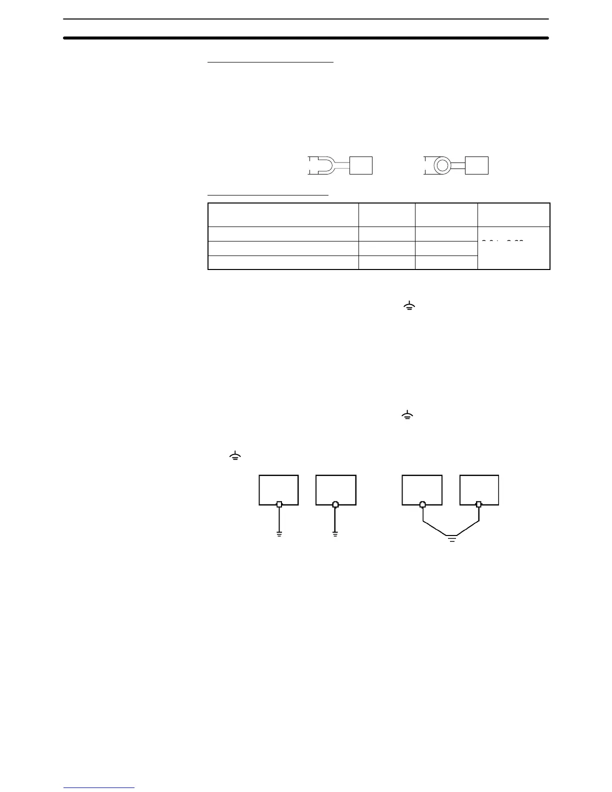
3-1-4 Grounding
The NT21 has a functional ground terminal ( ).
Carry out wiring under the following conditions.
1, 2, 3... 1. In cases where the distance between the NT21 is short and it is assumed
that
there is no potential dif
ference between grounds, ground as shown in
Fig. (a) below.
2. In cases where there is a potential difference between the grounds of the
NT21 and the host, ground as shown in Fig. (b). If there is some distance
between
the NT21 and host and grounding at a single point is dif
ficult, do not
connect the functional ground terminal ( ) of the NT21.
3. If
the NT21 is installed in the same panel as equipment that generates noise,
such as a motor or inverter, do not ground the functional ground terminal
(
) of the NT21.
Fig.
(a)
Fig. (b)
Ground to
100
Ω
max.
Ground at a
single point
NT21 Host NT21
Host
Note Carry
out grounding correctly in order to prevent operating errors due to noise.
3-2 Connecting Link Adapters
This section describes the installation of the NT-AL001 and NS-AL002 Link
Adapters, including the external dimensions, procedure for mounting and re-
moval,
and specifications. Refer to this information when designing the control
panel. For further details, refer to the Instruction Sheet supplied with the NT-
AL001 or NS-AL002.
3-2-1 Connecting an NS-AL002 Link Adapter
The NS-AL002 Link Adapter connects directly to the NT21’s serial port B and
converts
RS-232C communications to RS-422A or RS-485. The NT21 supplies

 Loading...


