3-4SectionConnecting a Bar Code Reader
29
3-4 Connecting a Bar Code Reader
Connecting
a bar code reader to the NT21 enables bar code data to
be read as
character
strings into character string input fields, and set in the character string
memory table.
In
order to use a bar code reader
, the Comm. A Method memory switch must be
set to Bar-Code Reader.
For
details on the method for inputting character strings with a bar code reader
,
refer
to
3-7 Input of Numeric V
alues and Character Strings
in the
NT31/NT31C/
NT631/NT631C/NT21 Programmable Terminal Reference Manual.
Note Make
sure that the power supply to
the bar code reader and the power supply to
the PT are both OFF before connecting or disconnecting the cable.
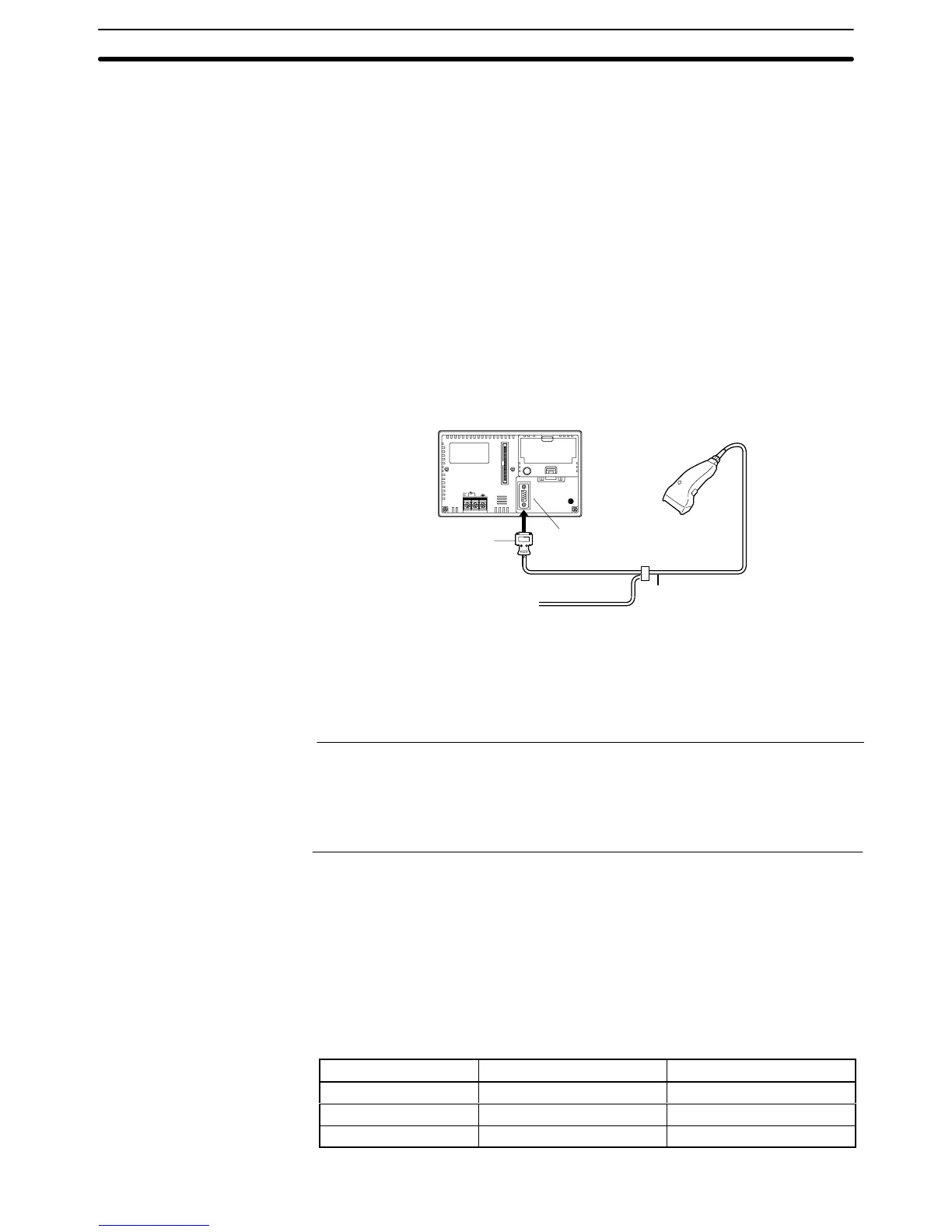
3-4-1 Connection Method
Connect
the bar code reader to serial port A of the NT21, as shown in the figure
below.
NT21
Bar code reader
9-pin connector
Serial port A
(RS-232C, 9-pin)
Connector cable
Bar code reader cable
Bar code reader
power supply cable
External
Power
Supply
Bar code reader must match the communication setting (3-4-2 Setting a Bar
Code
Reader
, page 29) and data format (
3-4-3 Data Format
, page
30) in order to
connect
to the
NT21. Please confirm the specification of the bar code reader be
-
fore using.
Reference: S The bar code reader must be connected to serial port A. This means that it
cannot
be connected at the same time as the NT Support T
ool. Note also that
when
a bar code reader is used, the host must be connected at serial port
B.
S Do
not use serial port A
’
s +5-V power supply as the bar code reader
’
s power
supply. Always supply power from an external power supply.
3-4-2 Setting a Bar Code Reader
After
connecting a bar code reader
, set the communication conditions and other
settings for it by selecting from the system menu.
At
the NT21, set the communication conditions for communication with the
bar
code
reader by using the memory switches, selecting from the options indicated
in
the table below
. Select from them according to communication conditions that
can be set at the bar code reader or other circumstances.
For more detailed information on the actual system menu operations, refer to
6-10 Setting the Bar Code Reader Input Function (page 144).
Item Possible Settings Default Setting
Data bits 7 or 8 bits 7 bits
Stop bits 1 or 2 bits 2 bits
Parity None, odd, even Even
Settings at the NT21

 Loading...


