3-2SectionConnecting Link Adapters
22
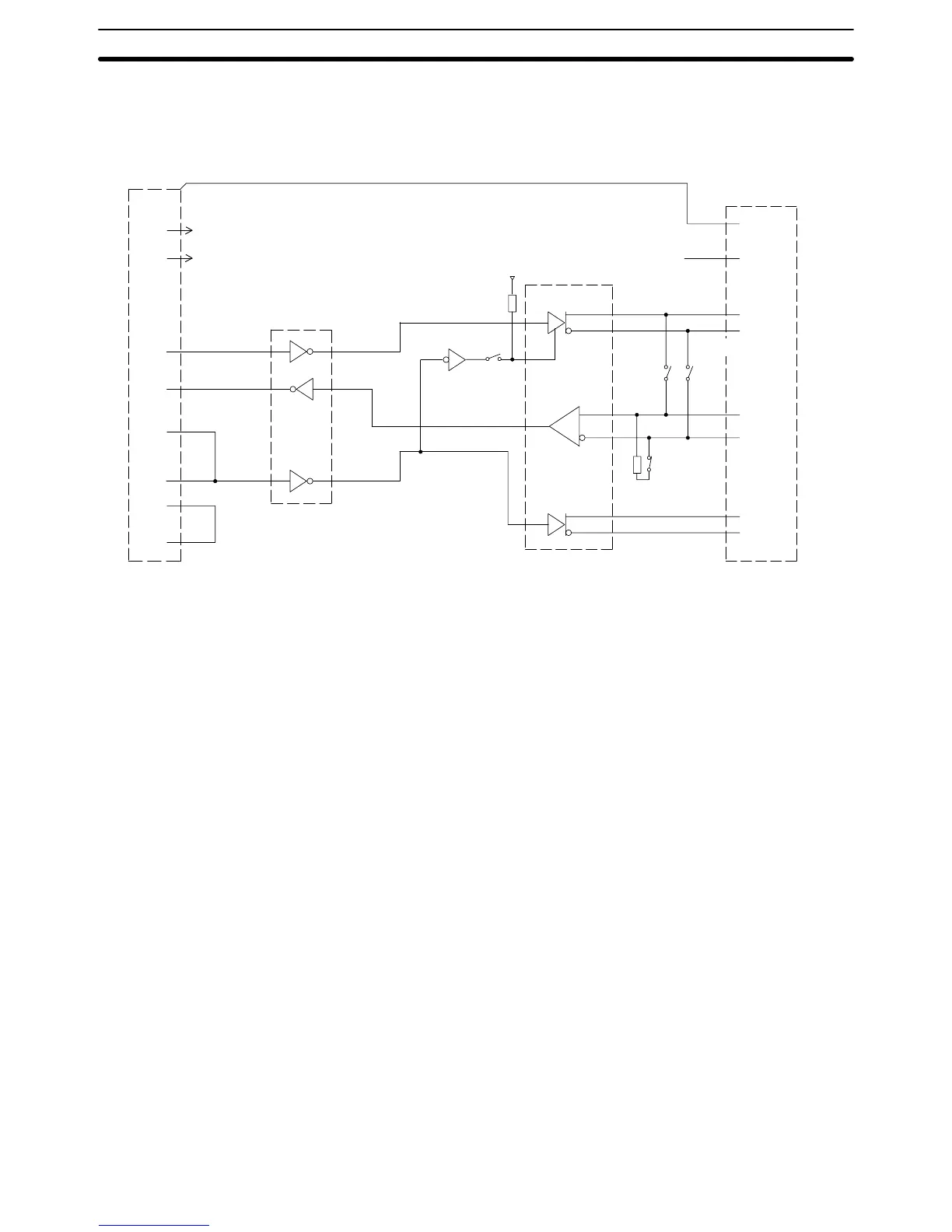
The
following diagram shows the
internal block diagram of the NS-AL002-E Link
Adapter. Refer to this diagram only when wiring custom cables or connecting
devices with special interfaces.
Terminating
resistance
D-SUB 9-pin Case
+5
V
SG
SD
RD
RS
CS
DR
ER
6
9
3
2
5
4
7
8
RS-232C
Dr/Rec
RS-422A/485 Dr/Rec
FG
1
5
3
7
6
2
4
8
SW1-2
NC
SDB
SDA
RDB
RDA
RSB
RSA
SW1-4
SW1-3
RS-232C
RS-422A/485
8-pin terminal block
2-wire/
4-wire
R
SW1-1
+5 V
R
3-2-2 Connecting an NT-AL001 Link Adapter
The
NS-AL001 Link Adapter connects to serial port A or B of the NT21 with an
RS-232C cable and converts the RS-232C communications to RS-422A or
RS-485. (Serial ports A and B cannot be used simultaneously.)
The
NT21 supplies +5 V power (150 mA max.)
to the Link Adapter through pin 6
of the RS-232C connector, so an external power supply is not required.
Note 1. The
RS-232C connector is not insulated from the RS-422A/RS-485 connec
-
tor within the NT-AL001 Link Adapter.
2. Always
turn
OFF the NT21’
s power supply before installing/removing a Link
Adapter or connecting/disconnecting cables.
Block Diagram

 Loading...


