Adjustment
13 - 3
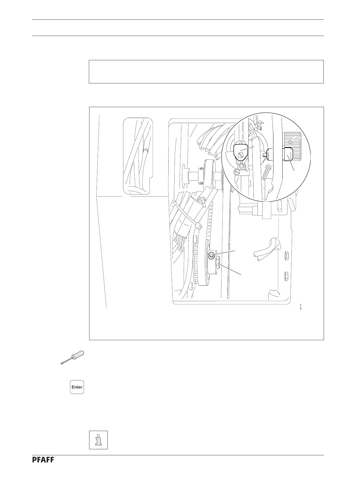
Fig. 13 - 02
1
3
4
2
3
13.05 Top needle bar position (reference position)
Requirement
Needle bar 4 should be positioned at its t.d.c. with access to one of the screws 1.
● Remove the needle.
● Loosen screws 1.
● Using the balance wheel, position the needle bar at its t.d.c. and lock it with locking pin 2
(part no. 61-111 635-92).
● Switch on the machine, select parameter 612.
● With screw 3 turn the motor shaft so that the value for parameter 612 is at "0".
● Confirm the value.
● Confirm the value with the enter key.
● Tighten screws 1 (to begin with only one screw is accessible).
● Switch off he machine and remove locking pin 2.
This setting can change again by ± 3 increments after checking.

 Loading...