Adjustment
13 - 21
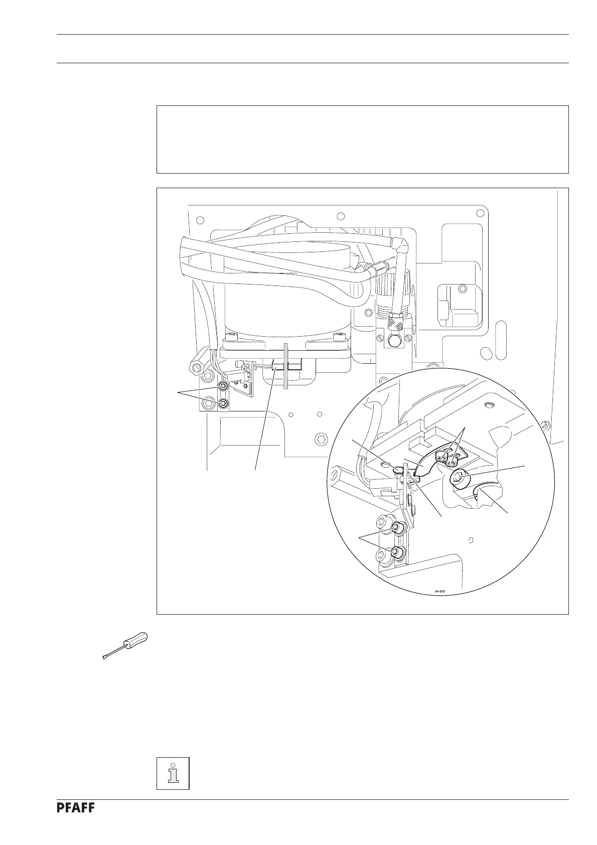
Fig. 13 - 19
4
1
3
4
5
6
7
2
8
13.21 Basic position of the button clamp drive
Requirement
1. After the machine has been switched on, it should be possible to lock lever 1 with the
needle rise gauge (2.4 mm).
2. Switch lug 5 should be positioned in the centre of the recess of the light barrier 3.
● Loosen screw 1.
● Switch on the machine.
● Adjust lever 2 in accordance with requirement 1 (lock with needle rise gauge).
● Tighten screw 1.
● Adjust light barrier 3 (screws 4) in accordance with requirement 2.
● With lever 1 locked, move the switch lug 5 (screws 6), until LED 7 lights up and then
move it back again until LED 7 has just extinguished.
● Switch off the machine and remove the needle rise gauge.
Spring clip 8 serves as an adjustment aid and should be touching lever 2. The
open side of the spring clip 8 should be in alignment with the clamp groove of
lever 2.

 Loading...