Section
(_C_o_n_n_e_c_ti_n--=g=----t_h_e_s-=.y_s_te_m
~)
CiS
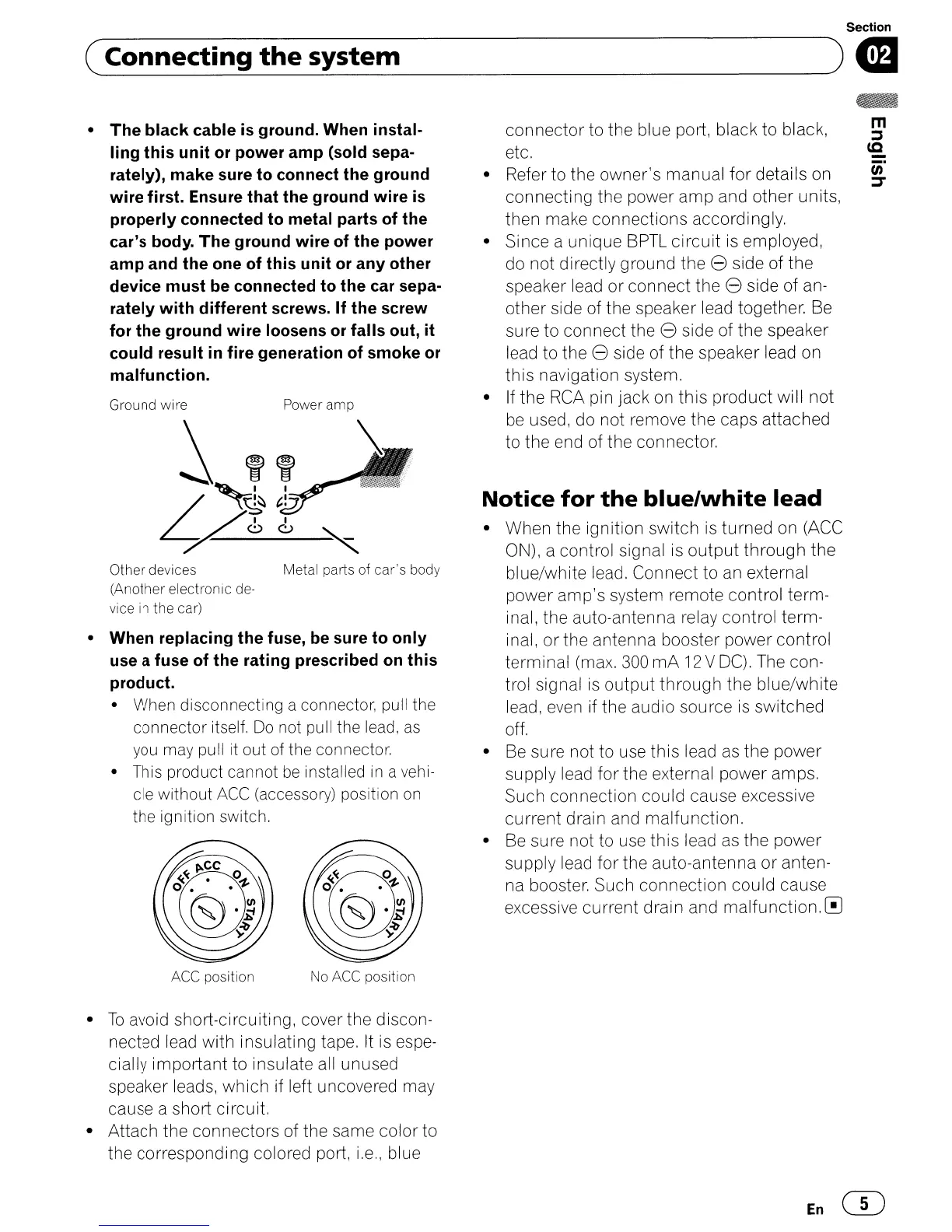
Other devices Metal parts of car's body
(Another electronic de-
vice
in
the car)
m
::s
cc
-
tn
::r
connector
to the blue port, black to black,
etc.
• Refer to the owner's manual
for
details on
connecting the power
amp
and other units,
then make connections accordingly,
• Since a unique BPTL
circuit
is
employed,
do not directly ground the
8 side of
the
speaker lead
or
connect the 8 side of an-
other side of the speaker lead together. Be
sure to connect the 8 side of the speaker
lead to the
8 side of the speaker lead on
this navigation system.
• If the
RCA
pin jack on
this
product will not
be
used, do not remove the caps attached
to the end of the connector,
Notice
for
the
blue/white
lead
• When the ignition switch
is
turned on (ACC
ON), a control signal
is
output
through
the
blue/white lead. Connect to
an
external
power amp's system remote control term-
inal, the auto-antenna relay control term-
inal,
or
the antenna booster power control
terminal (max.
300
mA
12
V
DC).
The con-
trol signal
is
output
through
the blue/white
lead,
even
if the audio source
is
switched
off.
•
Be
sure not to use this lead as the power
supply lead for the external power amps.
Such connection could cause excessive
current drain and malfunction.
• Be sure not to use this lead as the power
supply lead for the auto-antenna
or
anten-
na booster. Such connection could cause
excessive current drain and
malfunction.0
Power ampGround wire
•
The
black cable
is
ground. When instal-
ling this unit or power amp (sold sepa-
rately),
make
sure to connect the ground
wire first. Ensure that the ground wire
is
properly connected to metal parts of the
car's body.
The
ground wire of the power
amp
and the one of this unit or any other
device must be connected to the car sepa-
rately with different screws. If the screw
for the ground wire loosens
or
falls out, it
could result
in
fire generation of smoke
or
malfunction.
• When replacing the fuse, be sure to only
use a fuse of the rating prescribed
on
this
product.
• When disconnecting a connector, pull the
connector itself.
Do
not
pu
II
the
lead,
as
you
may
pull
It
out
of
the connector.
• This product cannot
be
installed
in
a
vehi-
cle without
ACC
(accessory) position
on
the ignition switch.
ACC
position No
ACC
position
•
To
avoid short-circuiting, cover the discon-
nected lead with insulating tape. It is espe-
cially important to insulate all unused
speaker leads,
which
if left uncovered may
cause a short circuit.
• Attach the connectors of the same color to
the corresponding colored port,
i,e"
blue
En
CD
 Loading...