EasyManua.ls Logo

Polaris RANGER 570 2020 User Manual

Polaris RANGER 570 2020
574 pages
To Next Page IconTo Next Page
To Previous Page IconTo Previous Page
Page #305 background image
4
9850043 R01 - 2017-2021 RANGER 500 / 570 Service Manual
© Copyright Polaris Inc.
4.9
6. Inspect the flywheel for corrosion, warping, and
damaged or missing components.
NOTICE
At this time measure flywheel run-out using a dial
indicator near the teeth on the flywheel. If the run-out
causes the CPS air gap to be out of tolerance, identify
whether the flywheel is out of round, or if the crankshaft
is bent.
If the resistance test, air gap test, and flywheel
inspection all test good, remove the flywheel and
verify the keyway is in good working order. If the
keyway is intact and problems persist, thoroughly
inspect the relevant wiring connections as a electrical
component or connection may persist.
7. Install the stator if removed (see Engine / Cooling
System chapter).
8. Install the stator cover if removed (see Engine /
Cooling System chapter).
9. Install a NEW or known good CPS (see the “CPS
Replacement” procedure).
10.Fill and bleed the coolant system (see Engine /
Cooling System chapter).
CPS REPLACEMENT
1. If not done already; disconnect the CPS harness
connector.
2. Using an 8 mm socket, remove the CPS retaining bolt
and remove the sensor from the stator cover.
3. Install new sensor using a light coating of oil on the
O-ring to aid installation.
4. Torque the CPS and heat shield retaining bolts (if
equipped) to specification.
TORQUE
CPS Retaining Bolt:
9 ft-lbs (12 Nm)
ENGINE ELECTRICAL

Table of Contents

Question and Answer IconNeed help?

Do you have a question about the Polaris RANGER 570 2020 and is the answer not in the manual?

Polaris RANGER 570 2020 Specifications

General IconGeneral
BrandPolaris
ModelRANGER 570 2020
CategoryOffroad Vehicle
LanguageEnglish

Summary

2017-2021 RANGER 500 / 570 Service Manual

FOREWORD

SAFETY WARNINGS

Explains signal words (DANGER, WARNING, CAUTION, NOTICE, IMPORTANT) and their meanings.

CHAPTER 1 : GENERAL INFORMATION

MASTER TORQUE TABLE

Comprehensive table of torque values for various components.

GENERAL SPECIFICATIONS

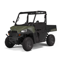
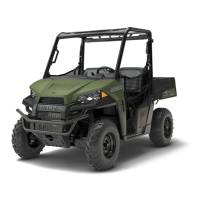
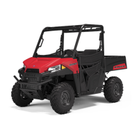
Provides detailed specifications for various RANGER models.

GENERAL DIAGNOSTICS

Overview of general diagnostics and guided symptom diagnostic procedures.

CHAPTER 2 : MAINTENANCE

ENGINE OIL LEVEL

Procedure for checking and maintaining engine oil level.

ELECTRICAL AND IGNITION SYSTEM

Details battery maintenance, testing, and spark plug service.

CHAPTER 3 : ENGINE / COOLING SYSTEM

ENGINE LUBRICATION SPECIFICATIONS

Details oil capacity, filter wrench, oil type, and pressure specifications.

OIL PRESSURE TEST

Procedure for testing engine oil pressure.

ENGINE SPECIFICATIONS

Provides detailed engine specifications for camshaft, cylinder head, and cylinder.

ENGINE REMOVAL

Step-by-step instructions for removing the engine assembly.

COOLING SYSTEM

Overview of the cooling system, specifications, and pressure testing.

PISTON / RINGS / CONNECTING ROD / CRANKSHAFT / BALANCE SHAFT

Details specifications for piston, rings, connecting rod, crankshaft, and balance shaft.

CHAPTER 4 : ENGINE ELECTRICAL

ELECTRONIC CONTROL UNIT (ECU)

Overview of the ECU's function, operation, and service.

ECU REPLACEMENT

Procedure for replacing the ECU with essential data transfer.

ELECTRONIC THROTTLE BODY (ETC)

Overview, testing, replacement, and learn procedure for the ETC.

CRANKSHAFT POSITION SENSOR (CPS)

Overview, testing, and replacement of the crankshaft position sensor.

CHAPTER 5 : FUEL SYSTEM

EFI OPERATION OVERVIEW

Explains the EFI system's role in engine performance and emissions.

FUEL SYSTEM TROUBLESHOOTING

Covers lean mixture, rich mixture, and poor idle conditions.

CHAPTER 6 : PVT SYSTEM

PVT SYSTEM OVERVIEW

Explains PVT system operation, including clutching and drive belt.

OVERHEATING / DIAGNOSIS

Procedures for diagnosing PVT overheating issues.

PVT DISASSEMBLY

Step-by-step instructions for disassembling the PVT system.

PVT ASSEMBLY

Procedures for assembling the PVT system components.

DRIVE BELT

Covers drive belt removal, inspection, and installation.

DRIVE CLUTCH SERVICE

Details drive clutch assembly view, disassembly, and inspection.

DRIVEN CLUTCH SERVICE

Details driven clutch assembly view, disassembly, and inspection.

PVT SYSTEM TROUBLESHOOTING

Troubleshooting guide for common PVT system issues.

CHAPTER 7 : TRANSMISSION

TRANSMISSION SERVICE

Procedures for transmission removal and installation.

TRANSMISSION INTERNALS SERVICE

Details differential operation and internal transmission service.

TROUBLESHOOTING CHECKLIST

Checklist for diagnosing shifting difficulties.

CHAPTER 8 : FINAL DRIVE

OPERATION, FRONT GEARCASE (4WDC)

Explains the operation of the front gearcase in 2x4, 4x4, and ADC modes.

CHAPTER 9 : STEERING / SUSPENSION

POWER STEERING UNIT REMOVAL

Steps for removing the power steering unit.

POWER STEERING UNIT INSTALLATION

Procedure for installing the power steering unit.

STEERING RACK REMOVAL / INSTALLATION (EPS)

Steps for removing and installing the steering rack on EPS models.

CHAPTER 10 : BRAKE SYSTEM

BRAKE SERVICE PROCEDURES

Steps for bleeding the brakes and changing the fluid.

BRAKES SQUEAL / POOR BRAKE PERFORMANCE

Troubleshooting guide for brake noise and poor performance.

CHAPTER 11 : BODY / FRAME

CHAPTER 12 : ELECTRICAL

DIAGNOSTIC MODE

Procedure to display diagnostic trouble codes (DTCs).

STARTER SYSTEM

Troubleshooting for starter motor issues and starter drive replacement.

Related product manuals