Matrix 832 / 832+ / 424
Page 128 RINS428-5
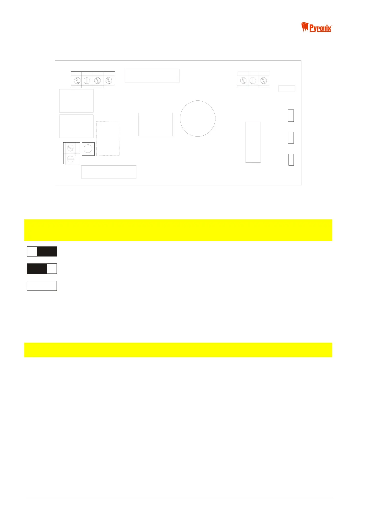
12.6 MX-BATT Battery Monitor Board
A
BAT OUT
B
A
T
I
N
17V ~
NCRT
B
C
+
+
-
-
Reset
Button
J1
The battery monitor board is a unique monitoring and test board for the Matrix range of control panels,
including the Matrix 832, 832+, 424 and Matrix 6.
Connect the battery monitor board to the control panel as illustrated below.
NOTE: If the zone connection is used, adjust header J1 to the relevant zone setting, i.e., Normally
Closed, End Of Line or Single End Of Line. The zone setting of the battery monitoring board must be
the same as that of the control panel.
Normally Closed
End Of Line
Single End Of Line
How the Battery Monitor Board Works
Once the mains supply is connected to the battery monitor board, it will continuously monitor the battery. If the
battery supply is good, the LED on the battery monitor board will be illuminated. If there is no mains supply
and the battery is low, the control system and battery monitoring board switch off, and the LED is no longer
illuminated.
NOTE: When a new battery is fitted and there is no mains supply, the engineer should press the reset
button to provide battery power to the board.
Battery Test
This option is disabled when the mains power is removed.
24 Hour Test Mode
24 Hour Test Mode is enabled by fitting header B. If enabled, and the battery voltage drops below 11.5 Volts,
the battery supply is cut off from the Matrix for 5 seconds (enabled by fitting header A).
RT
A low state on input RT can initiate a battery test.
Voltages
For details of operational voltages, see Section 1: Technical Specifications & System Overview.

 Loading...