SM 6-55 G147
Detailed
Descriptions
the terminal block [C], terminal plate [D], and the bias roller [E].
The high voltage supply board adjusts the current to the roller to keep a small but constant
current flow to ground through the belt, paper, and drum. If this current is not kept constant,
efficiency of toner transfer and paper separation will vary with paper thickness, type,
environmental condition, or changes in transfer belt surface resistance.
Correction for Paper Width and Thickness
A range of SP modes is available in order to adjust the machine so it can handle papers of
non-standard size and thickness.
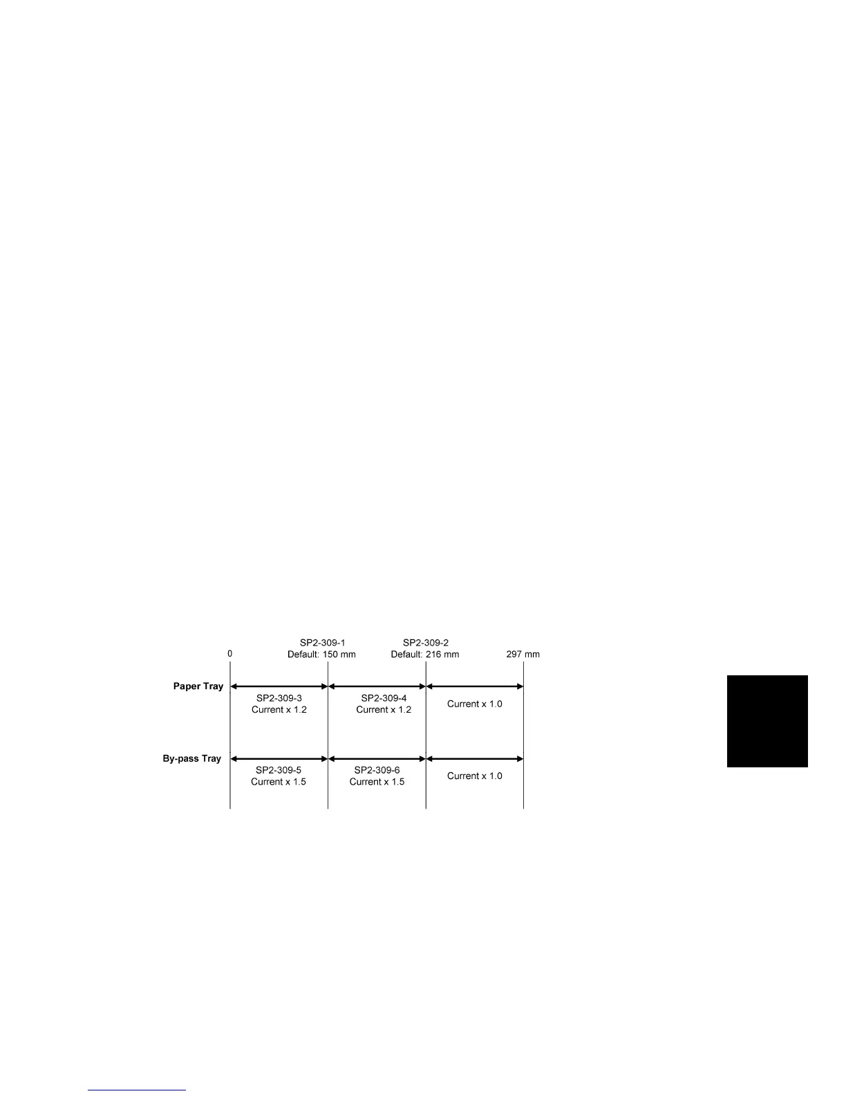
For paper width, there are two thresholds. The factory settings are 150 mm (5.9”) and 216
mm (8.5”). Below 216 mm, the transfer current can be increased. By default, the current is
multiplied by 1.2 for the main machine paper trays. For paper widths below 150 mm, the
transfer current can be set higher, but by default it is kept the same as the current for paper
widths below 216 mm. The higher current allows for the tendency of the current to flow
directly from the transfer belt to the drum and not through the paper which could cause an
insufficient amount of toner to transfer to narrow width paper.
Thick paper must be fed from the by-pass tray because SP modes are available only for the
by-pass tray in order to accommodate thick paper. By default, the current for paper narrower
than 216 mm is 1.5 times the normal current.
This illustration shows the SP modes, which control these currents. The base transfer
current (‘current’ in the diagram) depends on SP 2-301. This is different for various parts of
the image, and is different for the by-pass tray; see the next page for details.
Currents Applied to Leading Edge, Image Areas, and By-Pass Feed
Transfer current can also be adjusted for the leading edge and the image area, and for
by-pass feed. The timing for starting to apply leading edge current, for the switchover from
leading edge current to image area current, and for switching off at the trailing edge can also
be changed.
The table below lists the SP modes you can use to adjust these settings.
 Loading...