ELECTRICAL COMPONENT LAYOUT
SM 3 B538
Bridge Unit
B538
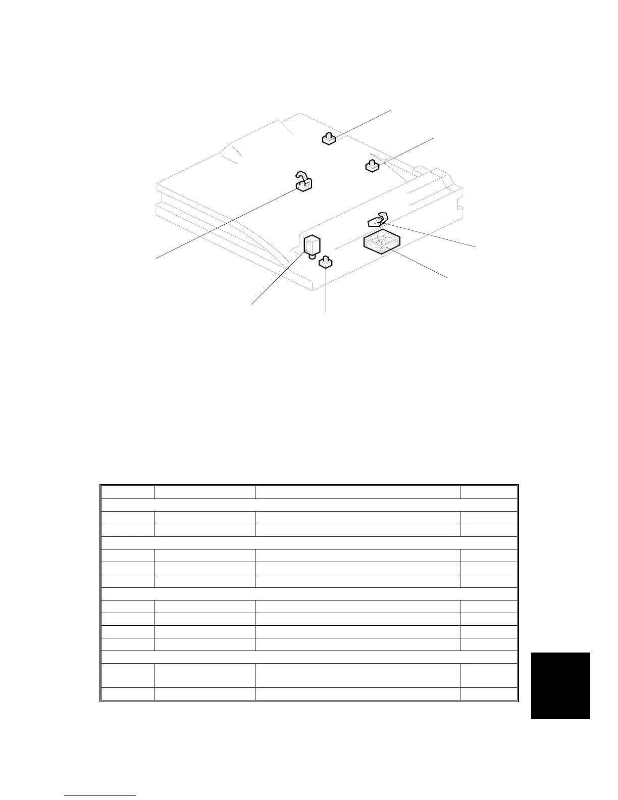
1.3 ELECTRICAL COMPONENT LAYOUT
1. Left Guide Switch
2. Right Guide Switch
3. Tray Exit Sensor
4. Cooling Fan Motor
5. Tray Exit Unit Switch
6. Junction Gate Solenoid
7. Relay Sensor
1.4 ELECTRICAL COMPONENT DESCRIPTION
Symbol Name Function Index No.
Motors
M1 Cooling Fan Cools the transport unit. 4
Sensors
S1 Tray Exit Checks for misfeeds. 3
S2 Relay Checks for misfeeds. 7
Switches
SW1 Tray Exit Unit Detects when the tray exit unit is opened. 5
SW2 Right Guide Detects when the right guide is opened. 2
SW3 Left Guide Detects when the left guide is opened. 1
Solenoids
SOL1
Junction Gate
Moves the junction gate to direct the paper
to the upper or left tray.
6
A688V501.WMF
5
1
2
3
4
6
7
 Loading...