Chapter 6 MATH and Measurements RIGOL
MSO2000A/DS2000A User’s Guide 6-35
Track Mode
In this mode, you can adjust the two cursors (cursor A and cursor B) to measure the
X and Y values on two different sources respectively. The points being measured on
cursor A and B are marked by an orange rectangle and rhombus respectively. When
the cursors are moved horizontally, the marks will position on the waveform
automatically. When the waveform is expanded or compressed horizontally, the
marks will track the points being marked at the last adjustment of the cursors.
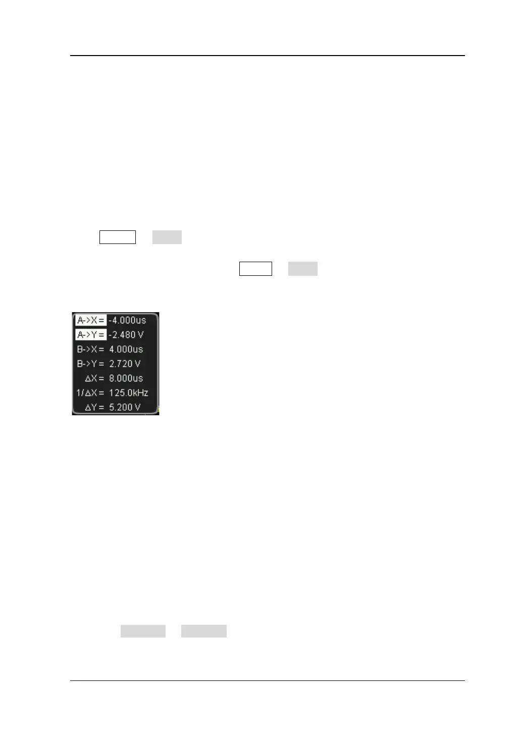
Press Cursor Mode “Track” to turn on the cursor track function and the
measurement results will be displayed at the upper left corner of the screen in the
following mode. You can also press MENU or Mode continuously to switch to
“Track”. When the measurement parameters are modified, the measurement results
will change accordingly.
A->X: the X value at cursor A. The X value takes the trigger position as reference
and “s” or “Hz” (when measuring FFT waveform) as its unit.
A->Y: the Y value at cursor A. The Y value takes the channel GND as reference
and use the same unit as the current source.
B->X: the X value at cursor B. The X value takes the trigger position as reference
and “s” or “Hz” (when measuring FFT waveform) as its unit.
B->Y: the Y value at cursor B. The Y value takes the channel GND as reference
and use the same unit as the current source.
△X: the horizontal difference between cursor A and B.
1/△X: the reciprocal of the horizontal difference between cursor A and B.
△Y: the vertical difference between cursor A and B.
1. Select Measurement Source
Press Cursor A or Cursor B to select the waveform of analog channels (CH1 or
CH2) or math operation results (MATH) as the measurement source of cursor A
www.GlobalTestSupply.com
Find Quality Products Online at: sales@GlobalTestSupply.com
 Loading...