RIGOL Chapter 8 Protocol Decoding
8-14 MSO2000A/DS2000A User’s Guide
SPI Decoding (Option)
SPI bus is based on the master-slave configuration and usually consists of chip select
line (CS), clock line (SCLK) and data line (SDA).
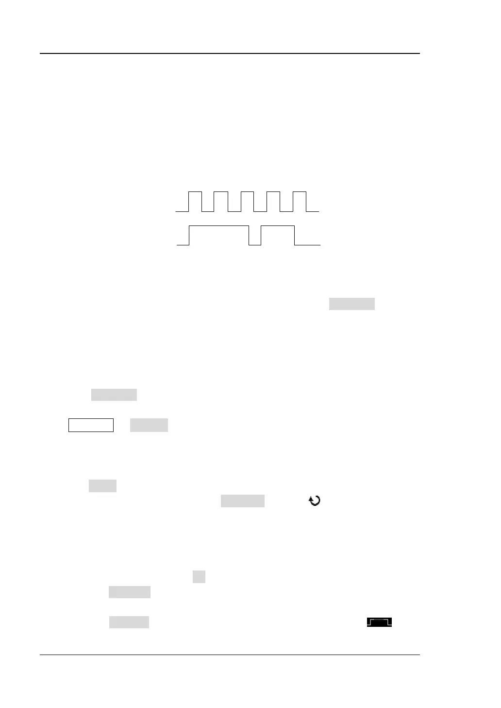
SCLK: sample the SDA on the clock rising edge or falling edge.
SDA: denote the data channel.
Figure 8-10 SPI Serial Bus
If the current trigger type of the trigger system is SPI, pressing CopyTrig can copy
the current SPI trigger settings (include the CS/TimeOut mode, clock channel, data
channel, data bits and so on) and apply them to the SPI decoding function as well as
set the polarity of the SDA data line to high. Then, if needed, you can still set the SPI
decoding parameters according to the introductions below.
Note: The copy function is only available when the current trigger type is “SPI”;
otherwise, CopyTrig is not available.
Press Decode1 Decode to select “SPI” and open the SPI decoding function
menu.
1. Decoding Mode Setting
Press Mode to select “TimeOut” or “CS”.
When “TimeOut” is selected, press TimeOut and use or the inner knob of
the navigation knob to adjust the timeout time at a relatively smaller step or turn
the outer knob of the navigation knob to adjust the timeout time at a relatively
larger step. The adjustable range is from 100 ns to 1 s. The default is 1 μs.
When “CS” is selected, press SS to enter the SS setting submenu. In this menu:
Press Channel to select any channel (CH1, CH2 or any channel of D0-D15)
as the CS channel.
Press Polarity to set the polarity of the chip select channel to
www.GlobalTestSupply.com
Find Quality Products Online at: sales@GlobalTestSupply.com
 Loading...