Rockwell Automation Publication 7000L-UM301F-EN-P - March 2020 269
Component Definition and Maintenance Chapter 5
3. Remove the screws and lift the ring lugs from the terminals to remove the
wires.
4. Release the locking mechanism located on each side of the ribbon cable
connector and pull the ribbon cable straight out to prevent bending the
pins.
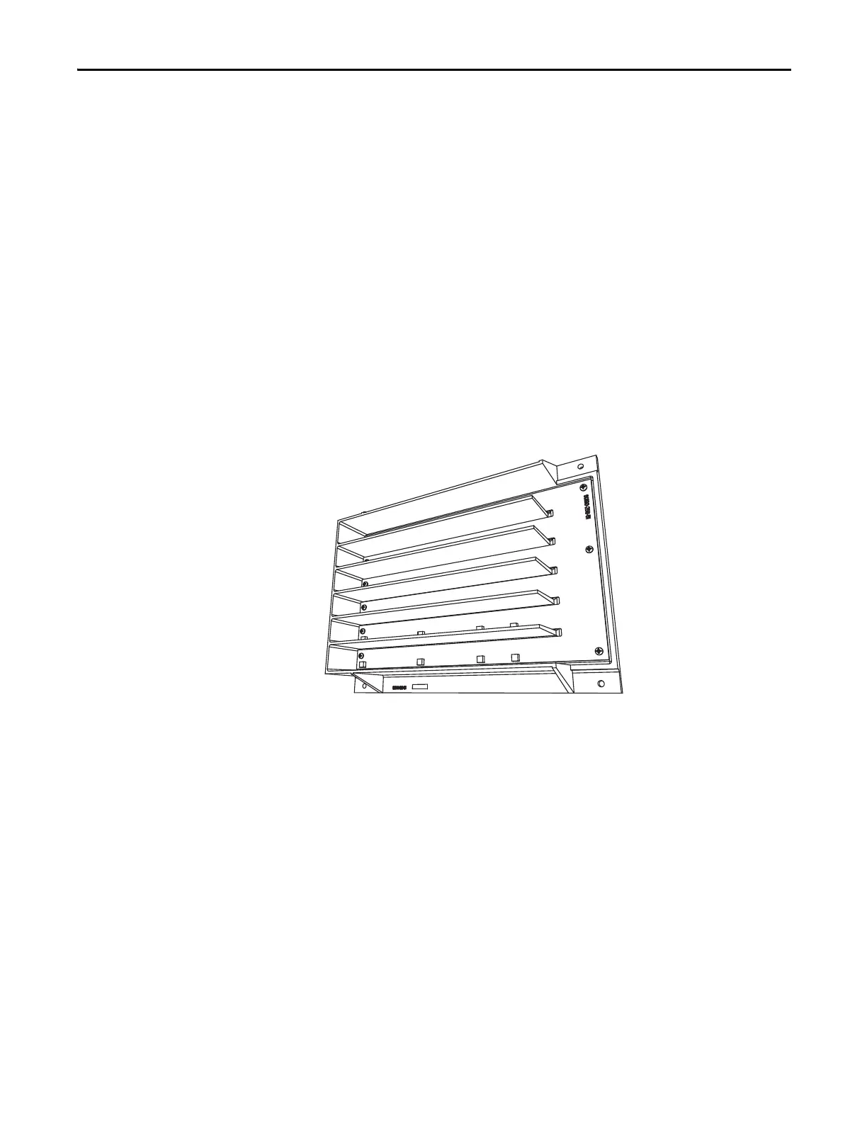
5. Remove the four nuts and washers that secure the assembly to the studs
welded to the frame.
6. Remove the old VSB and replace with the new VSB on the studs, using the
existing hardware to secure the assembly. Do not overtorque the
connections or you may break the studs.
7. Replace ring lugs on terminals. Plug in ribbon cables making sure that
cables are positioned properly and fitting is secure (locking mechanism is
engaged).
8. For personnel and equipment safety, ensure both grounding connections
are re-connected to the sensing board.
Figure 223 - Sensing Board with Mounting Hardware Placement
Input Transient Protection
Overview
Input transient protection is provided in two forms:
• Transient Suppression Network (TSN), or
• Surge Arresters
The TSN is optimized for 6P and 18 Pulse rectifier designs. Surge Arresters are
optimized for AFE and D2D rectifier designs.
 Loading...


