338 Rockwell Automation Publication 7000L-UM301F-EN-P - March 2020
Chapter 5 Component Definition and Maintenance
Fluid Conductivity
An in-line conductivity sensor (XS) (Figure 283) measures the fluid
conductivity. The sensor sends a signal to a meter mounted on the pump cabinet
door. Two conductivity switches are part of the meter. They are set at
conductivity of 1 µS/cm
3
for the annunciation warning and 2 µS/cm
3
for the trip
value.
Change the deionization cartridge when the conductivity rises to the warning
level.
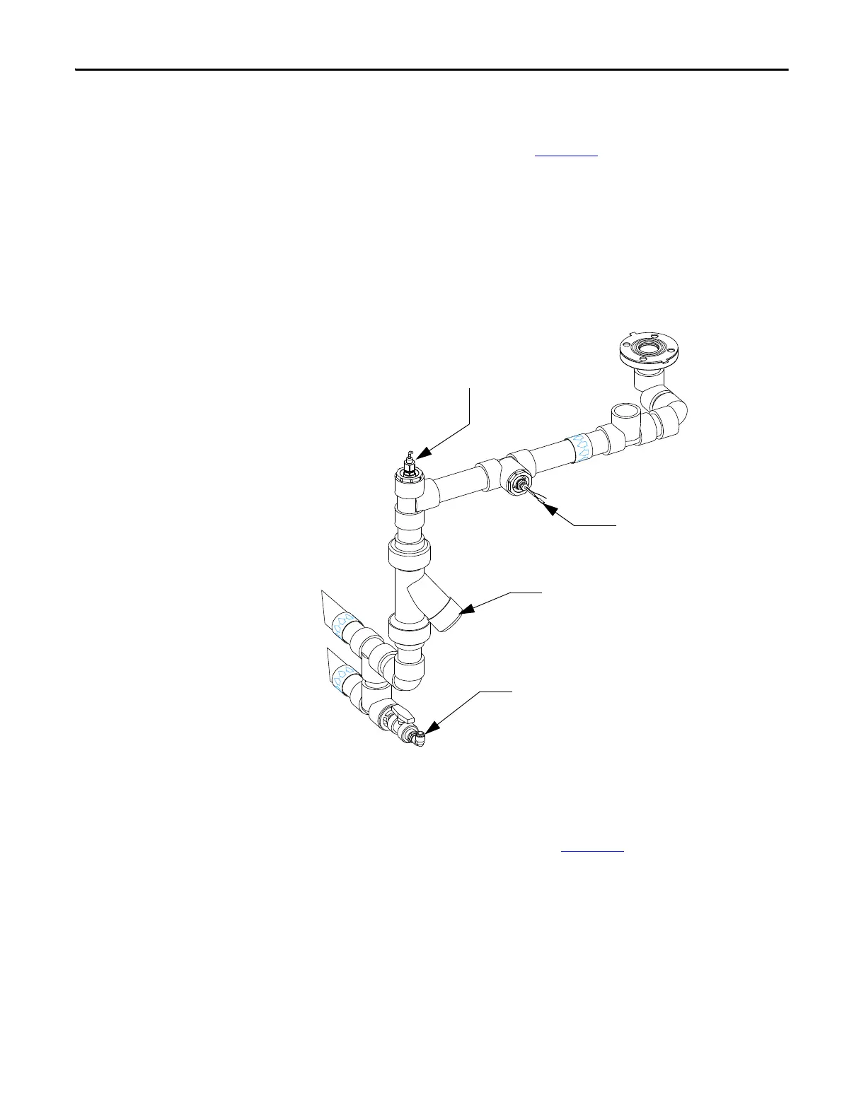
Figure 283 - Temperature and Conductivity Sensors
Temperature Sensor
This temperature sensor (TS1), shown in Figure 283, triggers the drive to shut
down when the fluid temperature entering the converter cabinet is too high. This
situation could occur if the air cooling of the heat exchanger is cut off due to fan
failure, plugging of the air paths, or failure of the thermostatic valve.
The following are the temperature values for alarm and trip signal:
1. When coolant temperature is greater than 48 °C (120 °F), an alarm signal
is initiated. It can only be reset when temperature reaches 38 °C (100 °F).
Conductivity Sensor x5
Strainer STR1
V6 Fill/Drain Valve
Temperature Sensor TS1
 Loading...


