Rockwell Automation Publication 7000L-UM301F-EN-P - March 2020 87
Drive Installation Chapter 2
Grounding Practices
The purpose of grounding is to:
• provide for the safety of personnel
• limit dangerous voltages on exposed parts with respect to ground
• facilitate proper overcurrent device operation under ground fault
conditions, and
• provide for electrical interference suppression
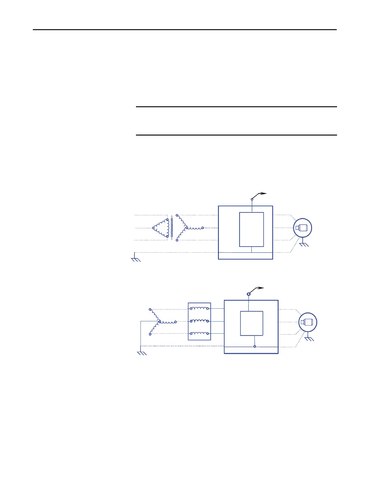
Refer to the grounding diagrams that follow for ground connections. The drive’s
main ground bus must be connected to the system ground. This ground bus is the
common ground point for all grounds internal to the drive.
Figure 70 - Ground Connection Diagram with Isolation Transformer
Figure 71 - Ground Connection Diagram with Line Reactor
Each power feeder from the substation transformer to the drive must be provided
with properly sized ground cables. Utilizing the conduit or cable armor as a
ground on its own is not adequate.
Note that if a drive isolation transformer is used, the WYE secondary neutral
point should not be grounded.
Each AC motor frame must be bonded to grounded building steel within 6 m
(20 feet) of its location and tied to the drive’s ground bus via ground wires within
Generally, the means used for external grounding of equipment should be in
accordance with the Canadian Electrical Code (CEC), C22.1 or the National
Electrical Code (NEC), NFPA 70 and applicable local codes.
ISOLATION
TRANSFORMER
AC
MOTOR
U (T1)
V (T2)
W (T3)
2U
2V
2W
GROUND BUS
Connected to the neutral point
of the output capacitor
OUTPUT
GROUND
NETWORK
ISOLATION
TRANSFORMER
AC
MOTOR
U (T1)
V (T2)
W (T3)
2U
2V
2W
GROUND BUS
Connected to the neutral point
of the output capacitor
OUTPUT
GROUND
NETWORK
AC
MOTOR
U (T1)
V (T2)
W (T3)
2U
2V
2W
GROUND BUS
AC LINE
REACTOR
TRANSFORMER
Connected to the neutral point
of the output capacitor
GROUND
FILTER
AC
MOTOR
U (T1)
V (T2)
W (T3)
2U
2V
2W
GROUND BUS
AC LINE
REACTOR
TRANSFORMER
Connected to the neutral point
of the output capacitor
GROUND
FILTER
 Loading...


