Rockwell Automation Publication 7000L-UM301F-EN-P - March 2020 309
Component Definition and Maintenance Chapter 5
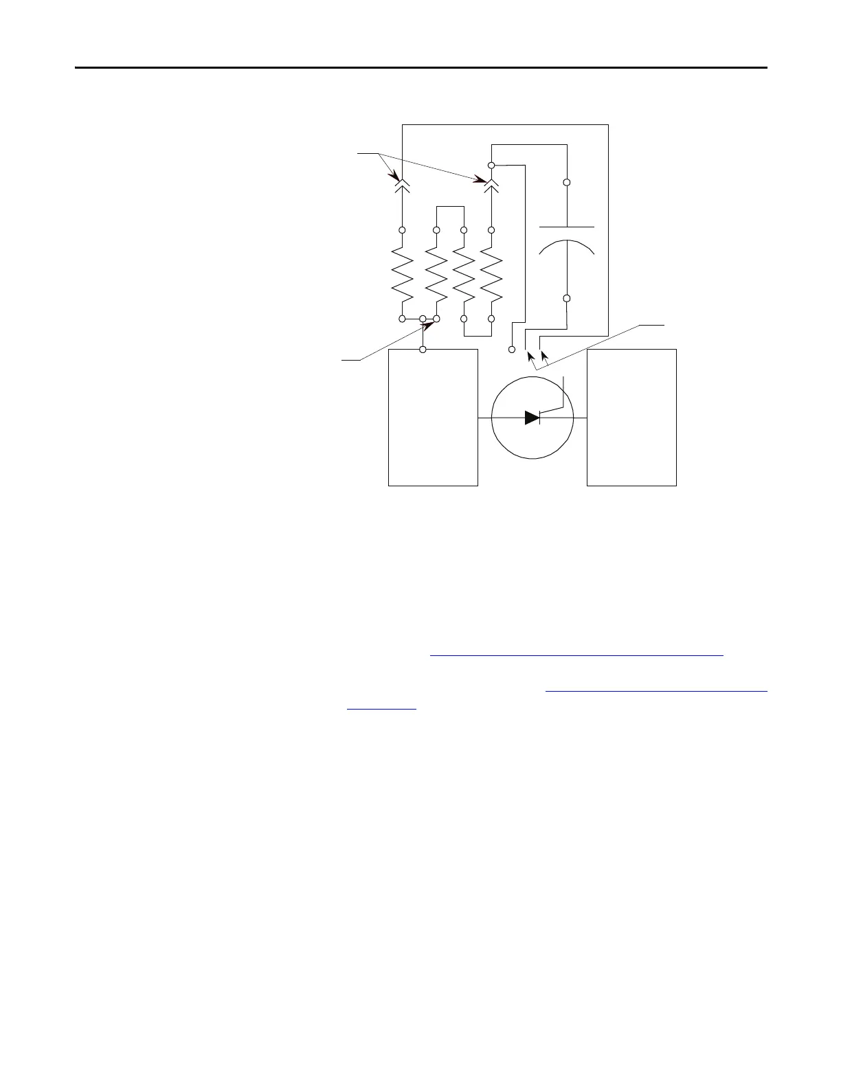
Figure 257 - SCR PowerCage Snubber Circuit Connections
Snubber and Sharing
Resistor Replacement
In the liquid cooled drive the sharing and snubber resistors can be replaced
independently. The sharing resistor is located in the same spot on every chill
block assembly, and the number of snubber resistors can vary with the drive
rating. The snubber and sharing resistors are part of the chill block assembly.
Servicing of resistors requires that the chill block be removed from the
PowerCage. Refer to
Chill Block Removal and Replacement on page 303.
1. Remove the chill block outlined in Chill Block Removal and Replacement
on page 303.
2. Note all connections for correct replacement.
3. Remove the screws holding the bus bars to the resistor terminals. The
position of the sharing resistor is common on all drive sizes. The number
of snubber resistors varies with the size of drive and application. Shown
below is a three-snubber resistor configuration. There can be up to 5
snubber resistors on each chill block.
Anode
Chillblock
Cathode
Chilblock
Disconnect Points
Rsh-1
Rsn-1
Cs-1
Cs-2
Rsn-2
To Gate Driver Board
TP
Rsh-2
 Loading...


