Rockwell Automation Publication 7000L-UM301F-EN-P - March 2020 279
Component Definition and Maintenance Chapter 5
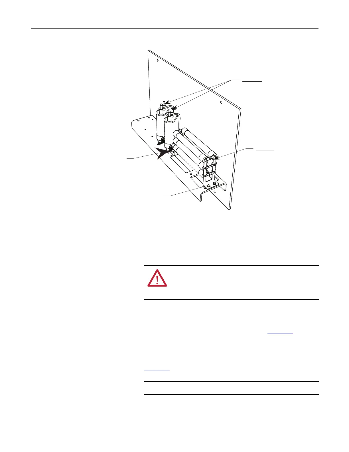
Figure 231 - Torque Values for Ground Filter Assembly
Ground Filter Replacement
The number of capacitors will vary depending on the system voltage.
1. Ensure there is no power to the equipment.
2. Note the position of the leads.
3. Disconnect the leads connected to the capacitor/resistor bank.
4. Loosen and remove mounting screws as indicated in Figure 232
and
remove the component.
5. Assemble the new component in the reverse order of disassembly.
6. Reattach the leads strictly adhering to the torque requirements outlined in
Figure 229
)
Loosen screws to
release capacitors
Remove screws for
replacing resistor bank
Important !
Torque on capacitor terminals
3,4 Nm (30 lb-in) maximum
Important!
Torque on resistor bank assembly
1,2 Nm (11.0 lb-in) maximum
ATTENTION: To prevent electrical shock, ensure the main power has
been disconnected before working on the capacitor. Verify that all
circuits are voltage free using a hot stick or appropriate voltage-
measuring device. Failure to do so may result in injury or death.
The maximum torque for the capacitor terminal is 3.4 Nm (30 lb-in).
 Loading...


