348 Rockwell Automation Publication 7000L-UM301F-EN-P - March 2020
Chapter 5 Component Definition and Maintenance
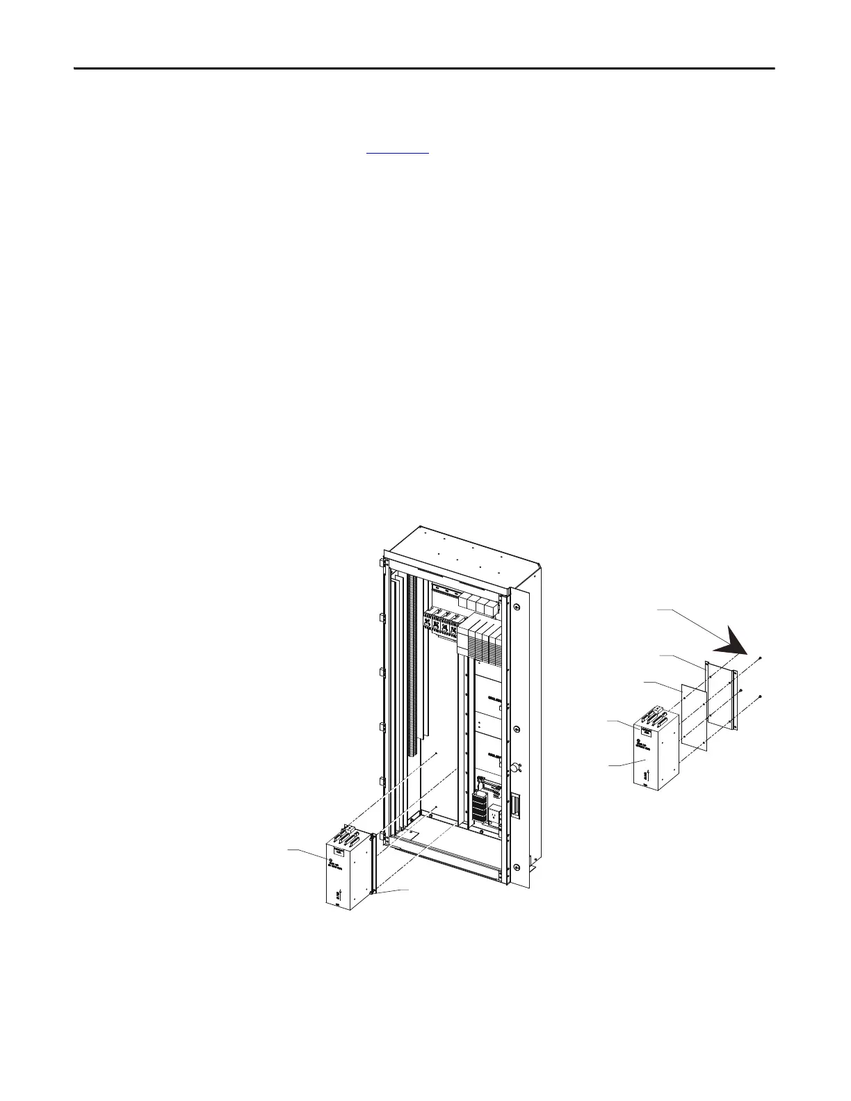
Replacement Procedure for DC/DC Power Supply
(Refer to Figure 289)
1. With the drive energized, check that all output voltages are present.
(View 1)
2. De-energize the drive, isolate and lock out the control power, and remove
all wire connections from the unit. (View 1)
3. Remove quantity of four M6 (H.H.T.R.S.) that will allow the DC/DC
Power Supply Assembly to be removed from the Low Voltage Panel.
(View 1)
4. Remove quantity of four M4 (P.H.M.S.) and Nylon Shoulder Washers
from the back of the Mounting Plate. (View 2)
5. Replace old DC/DC Power Supply with the new one. NOTE: Make sure
the Black Insulation is between the DC/DC Power Supply and the
Mounting Plate. Repeat Steps 4, 3, 2, 1 in this order to replace unit.
(View 2)
6. Ensure the ground wire of P4 plug is connected to the ground by M10
bolt.
Figure 289 - Replacement of DC/DC Power Supply
DC Power good indicator light
M6 (H.H.T.R.S.)
VIEW “1”
DC/DC
power supply
Part ID label
VIEW “2”
Black insulation
Mounting plate
M4 (P.H.M.S.) and
nylon shoulder washer
 Loading...


