5—VGA Main Display Home Screen
42 www.Roland.com Roland VS-2000 Owner’s Manual, Version Two Addendum
•
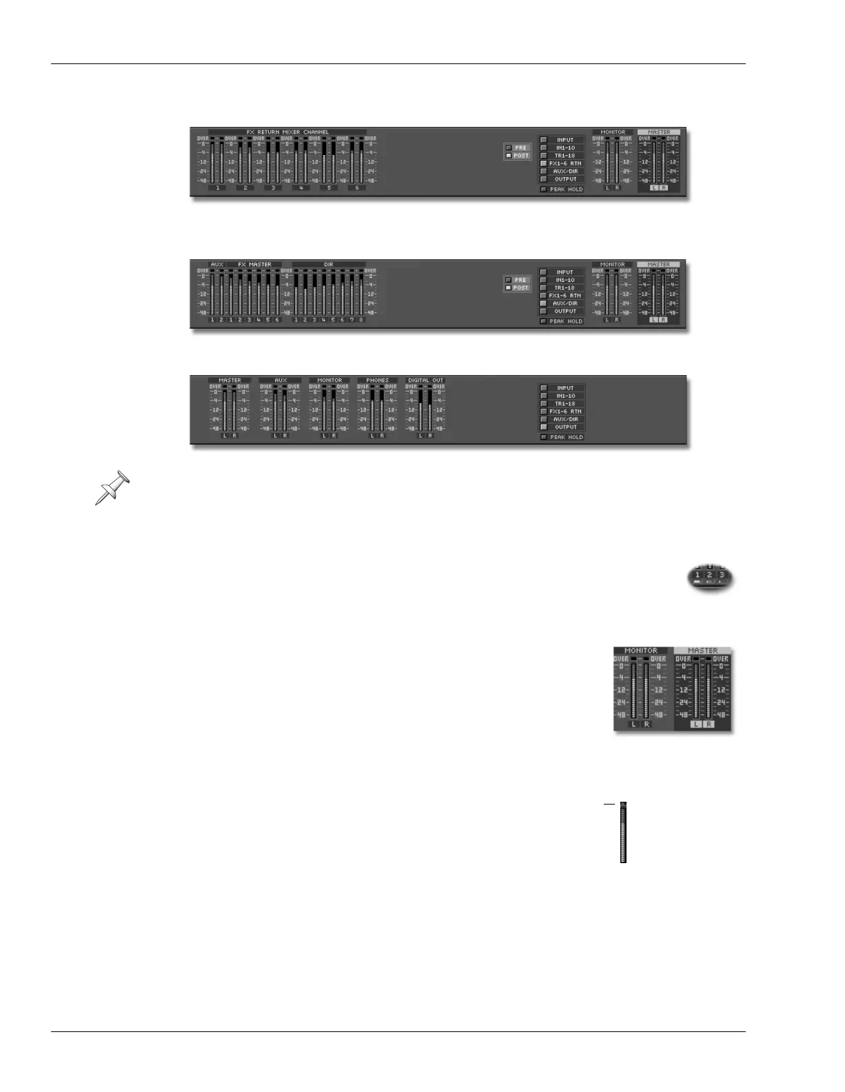
fx return channel levels
—signals as they exit the VS-2000’s internal effect processors.
•
Aux, FX and Direct path levels
—the two Aux master six FX master, and eight Direct
paths.
•
output levels
—signals as they exit the VS-2000’s output jacks and connectors.
Track Channel Meters TRACK STATUS Buttons
You can click the small button beneath a track channel meter to set the
corresponding hard disk recorder track’s status—the button acts just like
a TRACK STATUS button on the VS-2000, described on
Owner’s Manual
Page 176.
The MONITOR and MASTER Meters
The stereo MONITOR and MASTER bus output levels are
displayed at the right of the meters strip except when the input or
output meters are visible.
Working with the Meters Strip
Reading a Meter
Each meter in the meter strip contains a vertical stack
of segments that light to show the corresponding
signal’s level—the higher the stack, the louder the
signal. The segments are color-coded to help you see at
a glance how loud your signal is. If a signal exceeds
0dB, the meter’s OVER indicator lights to show you that
the signal’s too loud.
The number of active FX return channels depends on how many VS8F-2 effect
Expansion Boards or VS8F-3 Plug-in Expansion Boards are installed in your VS-2000.
See
Owner’s Manual
Page 55.
OVER
indicator
Red
—indicates
that the signal is
approaching 0dB.
Yellow
—warns
that you’re
nearing the red
area.
Green
—shows
that signal is
present.
VS2000v2Add.book 42 ページ 2005年4月8日 金曜日 午後2時24分
 Loading...