Switch Control Setup
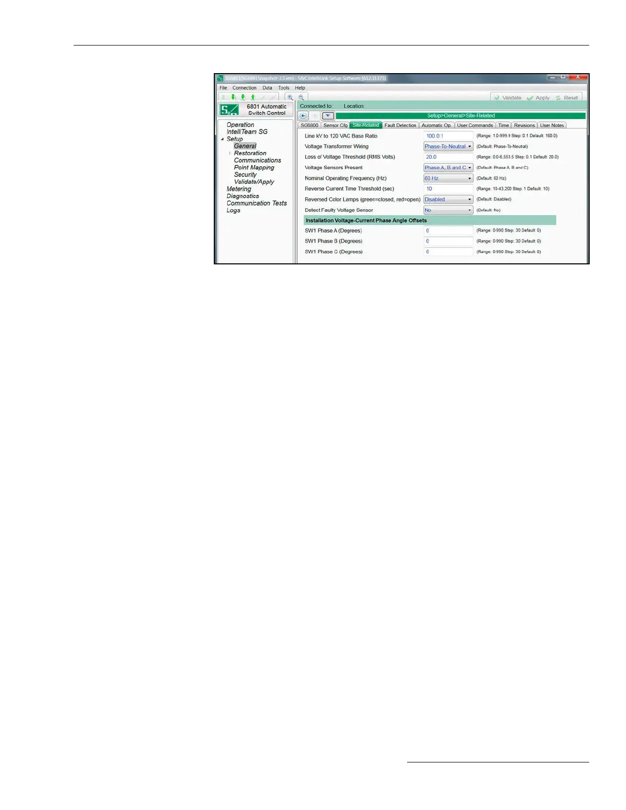
Figure 9. The Setup>General>Site-Related screen.
Line kV to 120 Vac Base Ratio
This is the voltage step-down ratio of all customer-load transformers on the feeder. See
Figure 9. The switch control records, displays, and manipulates voltages normalized on
a 120-volt or 240-volt base. This setting is the conversion ratio from line voltage to base
voltage. (Range: 1.0-999.9; Step: 0.1; Default: 100.0)
Enter the ratio for transformers wired the same way (phase to phase or phase to
neutral) as the value entered for the Voltage Transformer Wiring parameter in the
following examples:
Example #1—For a four-wire, wye, multi-grounded, 24.9-kV, phase-to-phase primary
distribution system with phase-to-neutral-connected customer single-phase transformers
rated 14,400/120 volts, enter a ratio of 120:1 and select the Phase-To-Neutral setting for
the Voltage Transformer Wiring parameter.
Example #2—For a three-wire, wye, 12-kV, phase-to-phase primary distribution
system with phase-to-phase connected customer transformers rated 12,000/120
volts, enter a ratio of 100:1, and select the Phase-To-Phase setting for the Voltage
Transformer Wiring parameter.
Voltage Transformer Wiring
This congures the switch control for customer-voltage reporting. The control uses this
information when calculating kvars. For delta voltage reporting, select the Phase-To-
Phase setting for this parameter. For wye voltage reporting, select the Phase-To-Neutral
setting for this parameter. (Default: Phase-To-Neutral)
Loss of Voltage Threshold (RMS Volts)
When the voltage level drops below this value (on a 120-volt base), the switch control
assumes power is no longer being supplied to the monitored phase. Normally leave this
at the factory default value 20.0 volts. Loss of voltage is detected by the switch control’s
true RMS transducer circuits, and voltage-loss detection qualication time can approach
600 ms. When the rst voltage loss will be less than 600 ms, congure the First-Reclose
Qualication Time setting on the Setup>General>Automatic Operation screen. For
more information about voltage-loss detection qualication time characteristics, see the
“Loss of Voltage Threshold” section in S&C Instruction Sheet 1045-530, “S&C 6800 Series
Automatic Switch Controls with IntelliTeam® SG Automatic Restoration system: Setup.”
(Range: 0.0-6,553.5; Step: 0.1; Default: 20.0)
When loss of voltage is detected, the Voltage Loss status indication will be active,
and the Phase Loss of Voltage status indication will be active for any phase below this
threshold.
Site-Related
Configuration
S&C Instruction Sheet 1045-530 25

 Loading...
