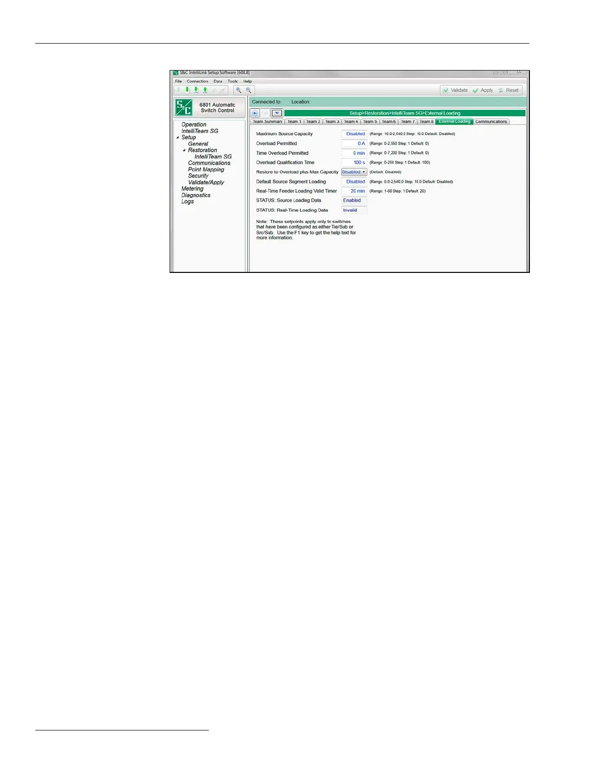
The screen in Figure 25 is used with feeder loading monitored at the substation breaker to
calculate the real-time excess capacity available when a transfer occurs. Both Maximum
Source Capacity and Default Source Segment Loading settings must only be set for
SRC/sub or tie/sub.
Maximum Source Capacity
This is the maximum feeder capacity (in amperes) as viewed from the substation end of
the feeder. This value represents the maximum three-phase average load the feeder can
carry at any time. (Range: 10-2,540 amps; Step: 10; Default: Disabled)
Overload Permitted
This value is added to the Maximum Source Capacity threshold and becomes the new
maximum load threshold that when exceeded requires immediate load shedding using
the Post Restoration Load Management feature. This setting is only applicable when
the IntelliTeam Post Restoration Load Management (PRLM) options are enabled.
Overloads above this level trigger a load-shedding event with no intentional delay to get
the load under the Overload Permitted threshold, and the Time Overload Permitted
timer will continue to count if it has not expired at this point.
The load will be shed based on the Team Load Priority setting configured for the
affected team. Otherwise, when load is above the Maximum Source Capacity value
but lower than the Overload Permitted threshold, it will be allowed to remain until the
Time Overload Permitted timer expires, which triggers an immediate load-shedding
event to get the load below the Maximum Source Capacity value. At this point, the
PRLM will identify the lowest priority team and shed its load.
If shedding that team’s load does not eliminate the overload condition, the PRLM
will find the next lowest priority team and shed its load. It will continue that process
until the load falls below the Maximum Source Capacity value, removing the overload
condition. No other overload conditions will be allowed until the system returns to its
Normal state. (Range: 0-2,550 amps; Step: 1; Default: 0)
Figure 25. The Setup>Restoration>IntelliTeam SG>External Loading screen.
Switch Control Setup
External Loading
56 S&C Instruction Sheet 1045-530

 Loading...
