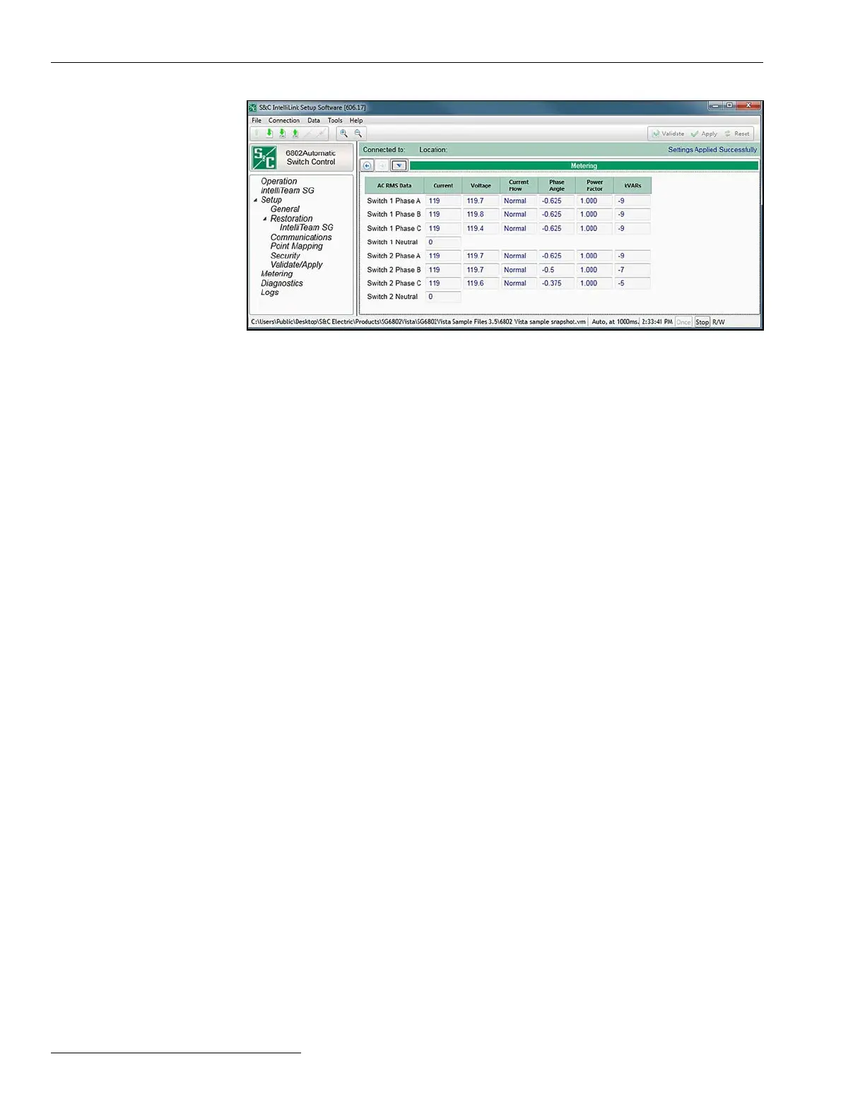
All values are time-averaged and reported locally and via SCADA on a one-second
interval. See Figure 11.
Primary Metering Data
Current
The current sensor output is scaled according to the calibration factors entered on the
Setup>General>Sensor Cong screen.
Voltage
True RMS voltage values are for each phase. This is the present value of the distribution
line voltage transformed to the nominal 120-Vac base. The switch control uses
this as the input-sensed value when it calculates the primary voltage. Either the
Phase-Neutral or Phase-Phase measurement setting may be selected, as congured
on the Setup>General>Site-Related screen. The second voltage is displayed only when
the “-E33” option is installed.
Current Flow
All three elds display a Normal condition when the switch control is properly congured
and power is owing through the circuit in the normal direction. The value in all three
elds changes to a Reverse condition when unusual circuit switching conditions cause
the direction of current to reverse.
Phase Angle
This is the calibrated phase angle or the offset of the current waveform referenced to
the voltage after all setup calibration factors have been applied. These corrected phase-
angle values will all be 0 ± 89.9 degrees when the switch control is properly congured.
Lagging phase angles are represented as values between 0 and 90 degrees. Leading
phase angles are represented as values between 0 and -90 degrees.
Power Factor
Power factor is calculated as the cosine of the corrected phase angle. The leading power
factor is represented by a negative number.
kvars
The switch control uses line-to-neutral voltage, current, and the sine of the phase angle
to calculate the kvar (kilovolts-amperes, reactive) value.
Figure 11. The Metering screen for a 6802 switch control.
Switch Control Setup
Metering Data
28 S&C Instruction Sheet 1045-530

 Loading...
