Switch Control Setup
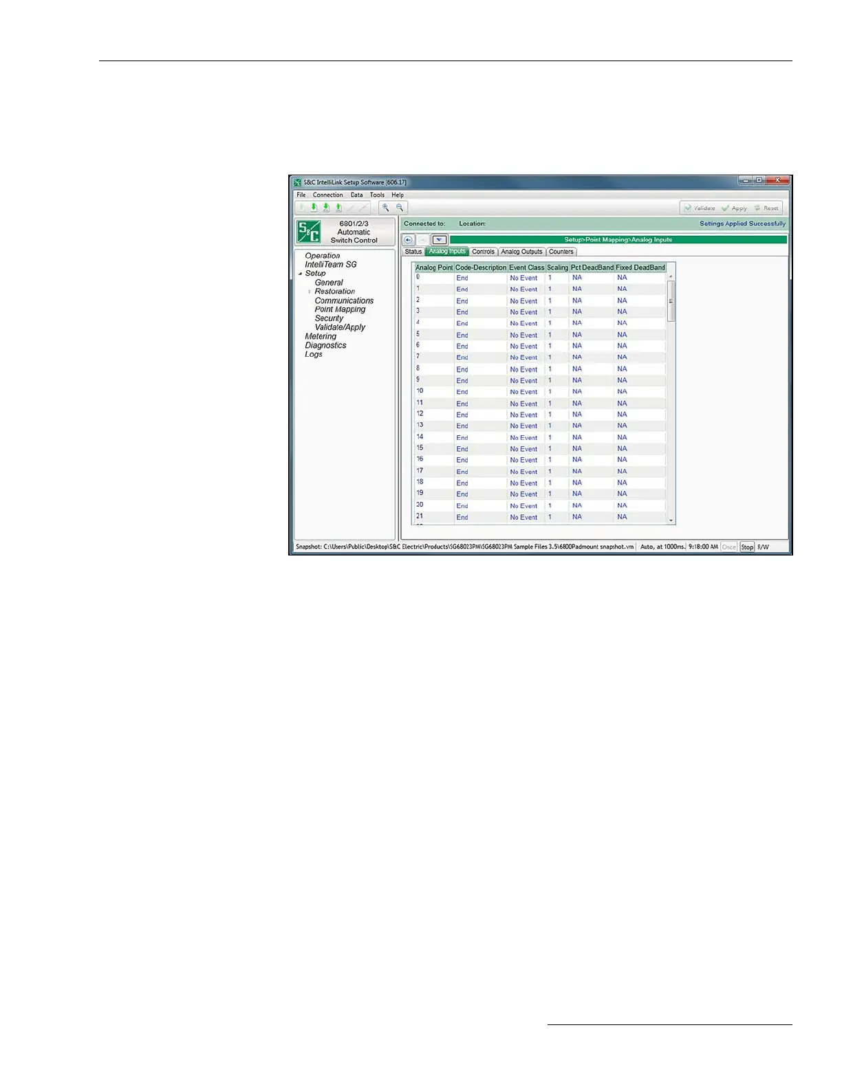
Figure 39. The Setup>Point Mapping>Analog Inputs screen.
The screen shown in Figure 39 contains conguration parameters for Analog Input points.
Map these points to make them available in the SCADA system.
Analog Point
This is the point number seen by the SCADA system in response to a static request, event
data request, or an unsolicited event response.
Code-Description
These are the point codes that represent specic analog inputs that may be assigned to
individual SCADA point numbers. Setting a Code-Description point code to the “End”
setting denes the end of the congured points list and the maximum number of analog
inputs that can be returned.
Analog Input points received from the external device may be mapped to individual
SCADA points. Enter the external device Analog point number (the range is 0 to 255) in
this column. See the external device documentation for definitions of its Analog points.
Event Class
This is the DNP event class assigned to this point. Specify Class 1, Class 2, Class 3, or
choose the No Event option to turn off event data reporting for this point.
Scaling
This is the scaling factor for the analog input data to match the analog input requirements
of the SCADA system.
DNP Analog Input
Point Mapping
Class
This is the DNP event class in which this point can be placed. Specify Class 1, Class 2,
Class 3, or choose the No Event option if event data reporting is turned off for this point.
S&C Instruction Sheet 1045-530 81

 Loading...
