Switch Control Setup
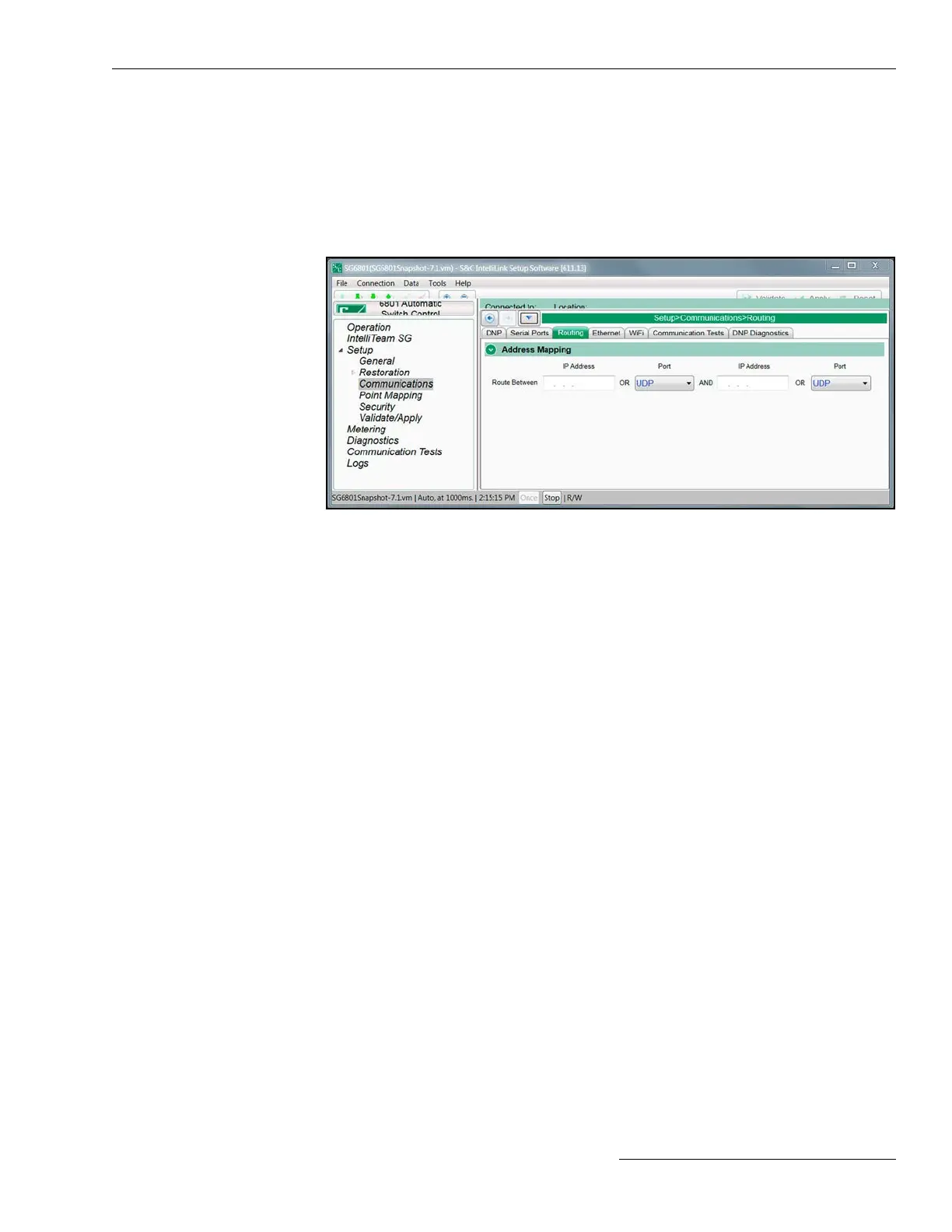
Figure 31. The Setup>Communications>Routing screen.
This screen can display routing information for up to 32 destination devices. See
Figure 31. If a message frame is received with a destination address other than the local
address, this information is used to redirect the message out an adjacent port. The frame
will be dropped if the destination address is not included in the routing table and a default
pass-through route has not been congured.
Address Mapping Section
RTU Address
When an incoming message frame is received that is not destined for the local device,
these addresses are searched to nd an active route.
IP Address
This parameter should be congured if the destination device is on an IP network. The
received frame will be transmitted out the local UDP port.
Port
This parameter should be congured if the destination device may be found through a
serial communications port. The received frame will be transmitted out the local serial
port.
Local Device DNP Address
This setting contains entries that dene default routing for messages that are addressed
to devices that were not found in the congured routing table and are not the local
device. This default routing performs a simple pass-through functionality between the
two interface points. If unknown trafc should not be be routed through this device,
leave these entries uncongured.
IP Addresses
This parameter should be congured if the intended destination device may be found
on the IP network. This will cause the received frame to be transmitted out the local
UDP port.
Routing
RTS Active Before/Following Xmit
This is the time, in milliseconds, the request to send (RTS) is active for this port before
and after a transmission takes place. The default value is usually suitable.
Interpacket Delay
This is the time in milliseconds, between individual message frames of a data stream.
Set this parameter appropriately for the radio.
S&C Instruction Sheet 1045-530 71

 Loading...
