Switch Control Setup
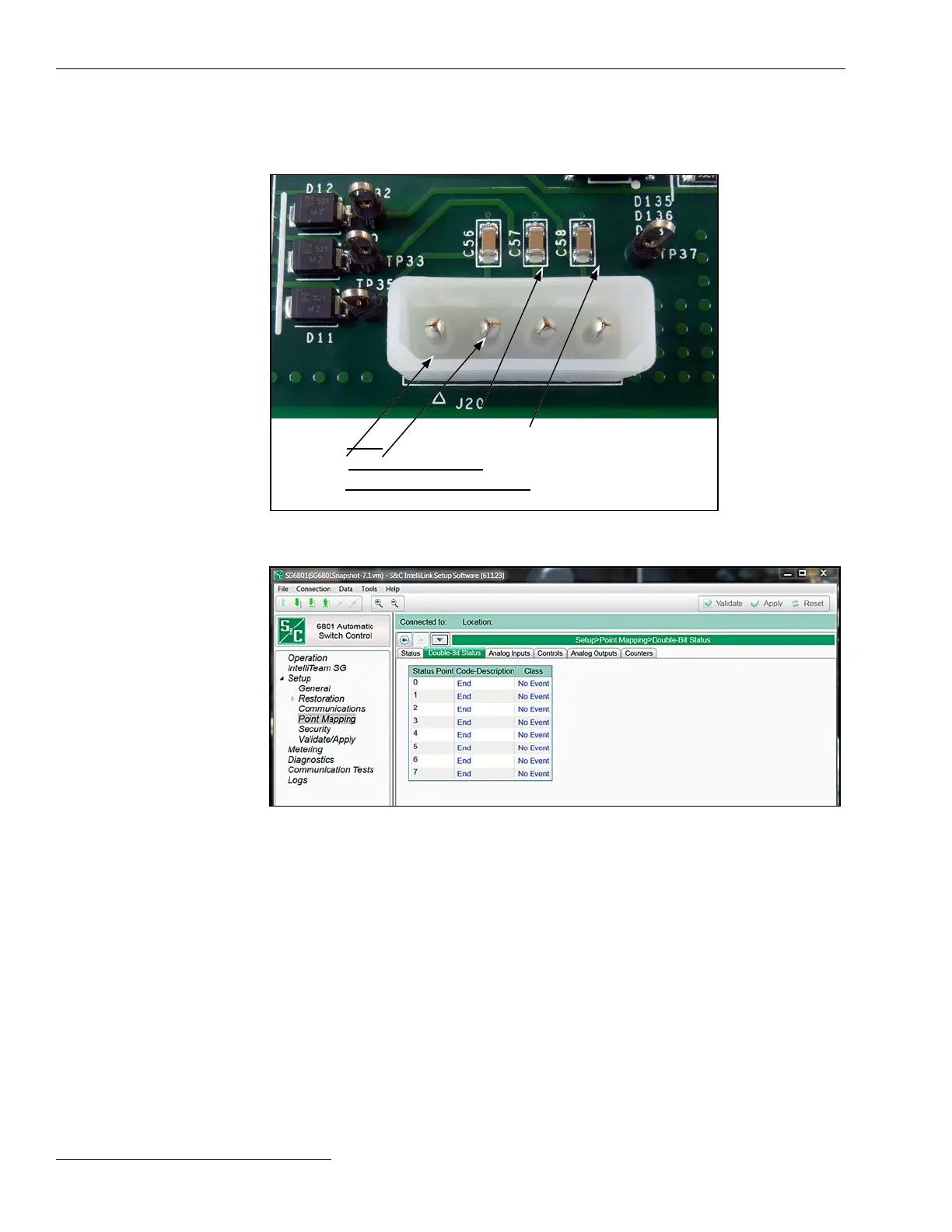
Figure 38. The Setup>Point Mapping>Double-Bit Status screen.
The screen shown in Figure 38 is visible when the Double Binary Inputs mode is set
to the Enabled state on the Setup>Communications>DNP screen. It has conguration
parameters for DNP Double-Bit status points. Map these points to make them available
in the SCADA system.
Status Point
This is the Double-Bit status point number the SCADA system will see in response to a
static or event data request, or an unsolicited event response.
Code-Description
These are the point codes representing specic status points that may be assigned to
individual SCADA point numbers. Setting a Code-Description point code to the “End”
setting denes the end of the congured points list and the maximum number of status
points that can be returned. All internal Double-Bit status points that can be mapped
to individual SCADA points are available in a pulldown list in the column next to the
SCADA point number the master station should receive it as.
Figure 37. Digital inputs connect at J20 on the PS/IO board.
Common
Input 1
Input 2
Input 3
DNP Double-Bit Status
Point Mapping
When the Require SCADA Acknowledgement setpoint is set to Yes, the User
Command section of the LCD screen includes an option to clear each of the congured
user-dened inputs. (Press ENTER to run command: Clear User Input n)
80 S&C Instruction Sheet 1045-530

 Loading...
