Switch Control Setup
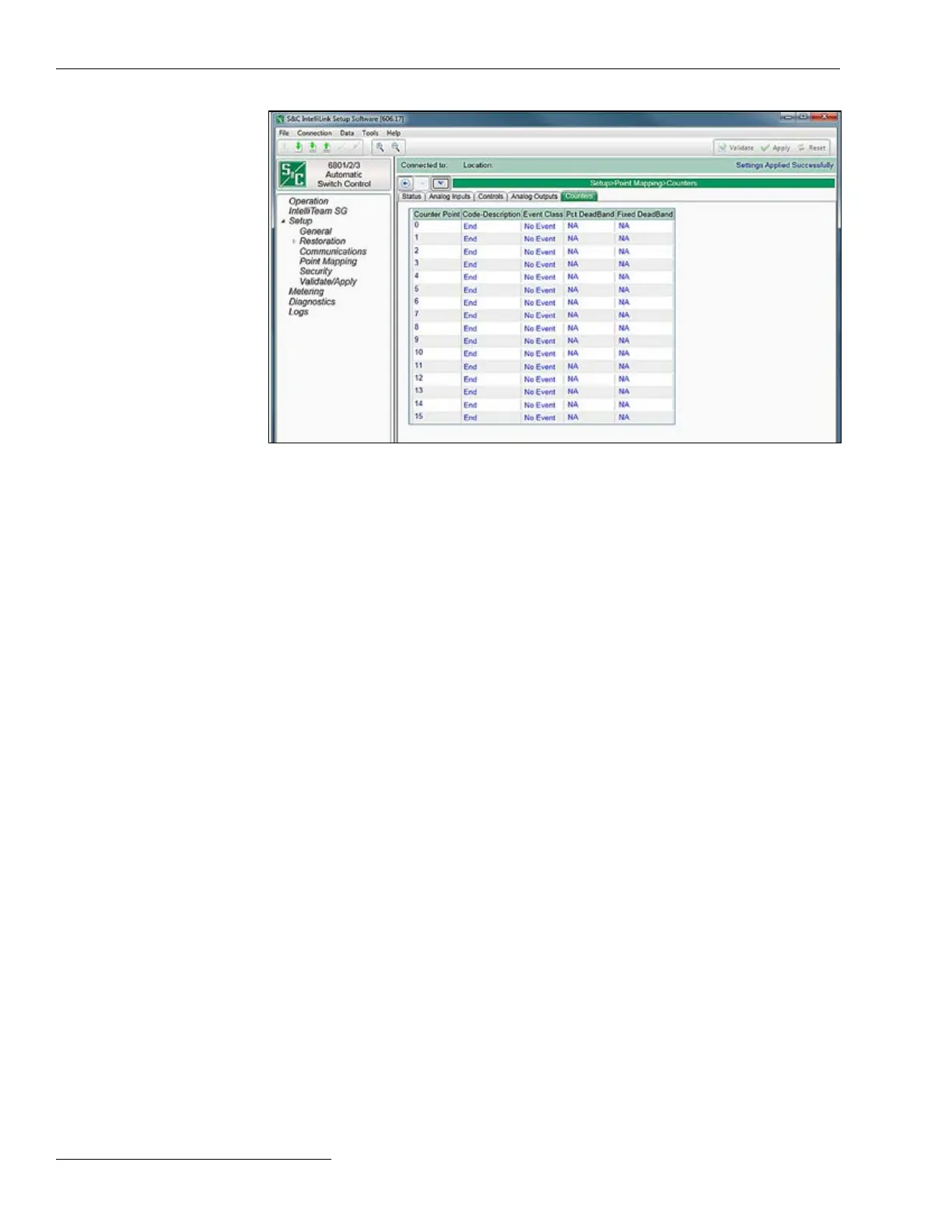
Figure 42. The Setup>Point Mapping>Counter Point Mapping screen.
The screen shown in Figure 42 contains conguration parameters for Counter points.
Map these points to make them available in the SCADA system.
Counter Point
This is the point number the SCADA system will use in response to a static or event data
request or an unsolicited event response.
Code-Description
This is the point codes representing specic Counter points that may be assigned to
individual SCADA point numbers. Setting a Code-Description point code to the “End”
setting denes the end of the congured points list and the maximum number of Counter
points that can be returned. All Counter points that can be mapped to individual SCADA
points are also displayed on the Logs/Special Events screen.
Evt Class
This is the DNP event class in which this point can be placed. Specify Class 1, Class 2,
Class 3, or choose the No Event option to turn off event data reporting for this point.
Pct DeadBand
This is the deadband range expressed as a percentage of the previously reported counter
point data. If the counter point data associated with this point exceed the range in either
a positive or negative direction, the information will be included in the next event report.
Choose the N/A option to turn off deadband reporting as a percentage of the previously
reported counter point data.
Fixed Deadband
This is the deadband range expressed as a xed value relative to the previously reported
counter point data. If the counter point data associated with this point exceed the range
in either a positive or negative direction, the information will be included in the next event
report. Choose the N/A option to turn off deadband reporting as a xed value relative to
the previously reported counter point data.
DNP Counter Point
Mapping
84 S&C Instruction Sheet 1045-530

 Loading...
