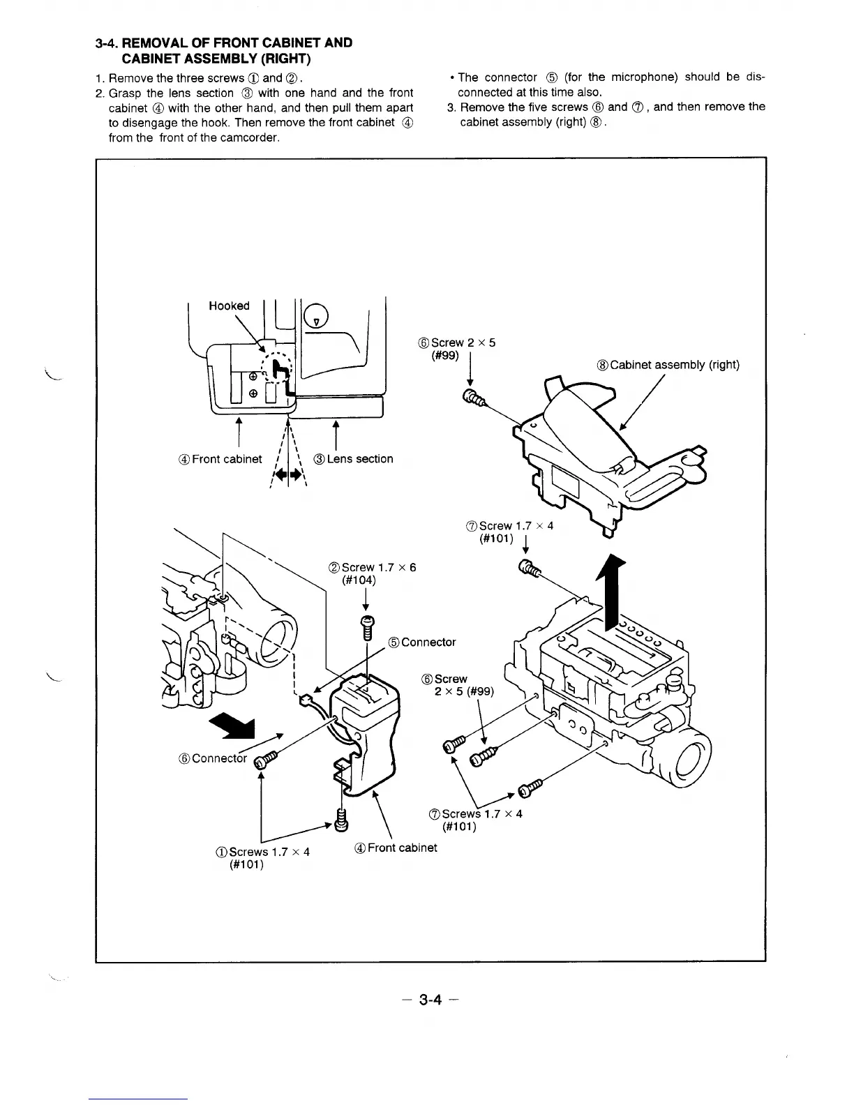
3-4. REMOVAL OF FRONT CABINET AND
CABINET ASSEMBLY (RIGHT)
1.
Remove the three screws@ and @.
● The connector 6 (for the microphone) should be dis-
2. Gras~ the lens section @ with one hand and the front
connected at this time also.
cabinet @ with the other hand, and then pull them apart
3. Remove the five screws @ and @, and then remove the
to disengage the hook. Then remove the front cabinet @
cabinet assembly (right) @.
from the front of the camcorder.
@FrOTOn
@Screw 2 x 5
(#99)
I
@Cabinet assembly (right)
.2 /
@. Screw1.7 x 4
(#lol)
4
v
I A\
I /@ \
- (#lol)
w
@Screws 1.7 x 4
@Front cabinet
(#1 01)
– 3-4 –
 Loading...