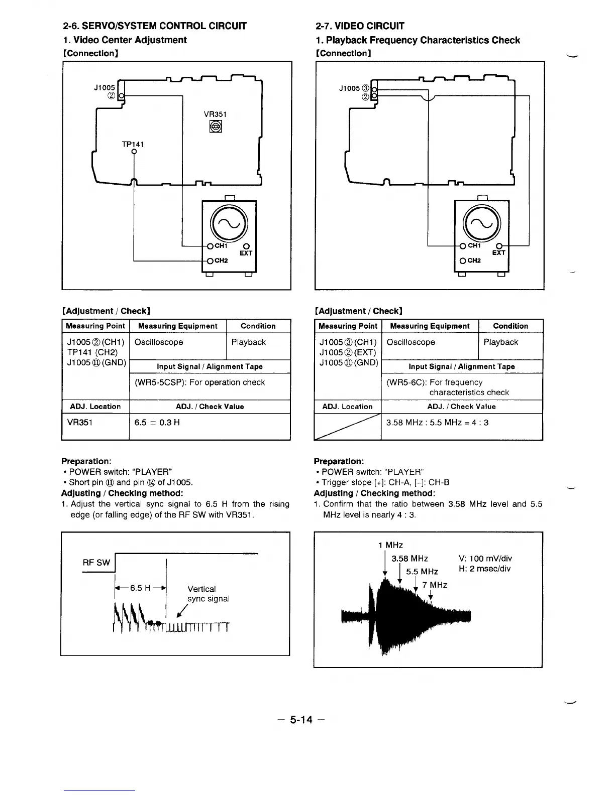
2-6. SERVO/SYSTEM CONTROL CIRCUIT
1. Video Center Adjustment
[Connection]
2-7. VIDEO CIRCUIT
1. Playback Frequency Characteristics Check
[Connection]
J1OO5
@
VR351
I
I n
[Adjustment / Check]
Meaauring point I Measuring Equipment
Condition
~~w:)~
Input Signal / Alignment Tape
(WR5-5CSP): For operation check
ADJ. Location
ADJ. / Check Value
VR351
6.5 ~ 13.3H
Preparation:
● POWER switch: “PLAYER”
● Short pin @ and pin @ of J1oo5.
Adjusting / Checking method:
1. Adjust the vertical sync signal to 6.5 H from the rising
edge (or falling edge) of the RF SW with VR351.
RF SW
“0-
—
[Adjustment / Check]
Meaauring Point I Meaauring Equipment I
Condition
Jloo5@(cHl)
Oscilloscope
Playback
J1 005@ (EXT)
Jloo5@(GND)
Input Signal / Alignment Tape
(WR5-6C): For frequency
characteristics check
ADJ. Location
ADJ. / Check Value
3.58 MHz :5.5 MHz=4 :3
Preparation:
● POWER switch: “PLAYER”
● Trigger slope [+]: CH-A, [–]: CH-B
Adjusting / Checking method:
1, Confirm that the ratio between 3.58 MHz level and 5.5
MHz level is nearly 4:3.
1 MHz
1
3.58 MHz
V: 100 mV/div
I 5.5 MHz
H: 2 msec/div
.-
– 5-14 –
 Loading...