3-7. REMOVAL OF CP1 BOARD AND MECHANISM
ASSEMBLY
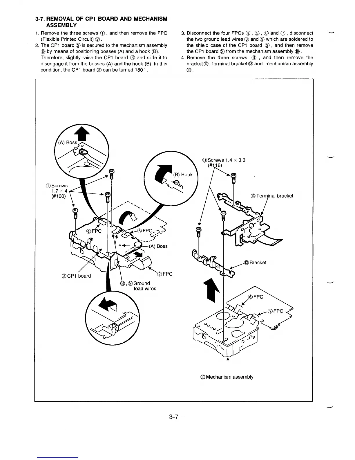
1.
Remove the three screws 0, and then remove the FPC 3. Disconnect the four FPCS o, 0, 0 and o, disconnect “-
(Flexible Printed Circuit) Q. the two ground lead wires B and a which are soldered to
2. The CP1 board o is secured to the mechanism assembly the shield case of the CP1 board 0, and then remove
o by means of positioning bosses (A) and a hook (B), the CP1 board ~ from the mechanism assembly o.
Therefore, slightly raise the CP1 board o and slide it to 4. Remove the three screws Q , and then remove the
disengage it from the bosses (A) and the hook (B). In this bracket o, terminal bracket o and mechanism assembly
condition, the CP1 board o can be turned 1800.
@.
n
4
7ji&n
oScrews 1.4 x 3.3
)
Hook
(#1 16)
1%
@cPl I
WMk I
,@
Bracket
/
L-
board
\\
‘B FPC
w%
o, QGround
lead wires
. 1
W
<
1
A
o Mechanism assembly
– 3-7 –
 Loading...