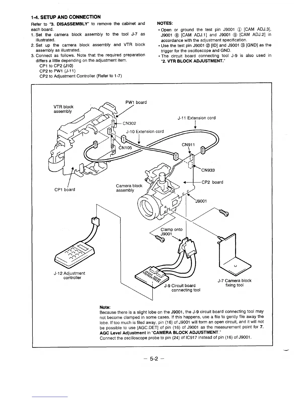
1-4. SETUP AND CONNECTION
Refer to “3. DISASSEMBLY to remove the cabinet and
NOTES:
each board.
I. Set the camera block assembly to the tool J-7 as
● Open or ground the test pin J9001 O [CAM ADJ.3],
J9001 (8J [CAM ADJ.1 ] and J9001 Q [CAM ADJ.2] in
illustrated.
2. Set up the camera block assembly and VTR block
accordance with the adjustment specification.
● Use the test pin J9001 o [ID] and J9001 O [GND] as the
assembly as illustrated.
3. Connect as follows. Note that the required preparation
trigger for the oscilloscope and GND.
differs a little depending on the adjustment item.
● The circuit board connecting tool J-9 is also used in
CP1 to CP2 (J1O)
“2. VTR BLOCK ADJUSTMENT.”
cP2 to PW1 (J-11)
CP2 to Adjustment Controller (Refer to 1-7)
4
\
PW1 board
VTR block
assembly
/
/
J-1 1 Extension cord
/
r CN302
1
>>C -1.
J-1 O Extension cord
~
K*~
L-!
CN933
Camera block
CP2 board
assembly
-c
I
CP1 board
w
v“
11
J-1 2 Adjustment
O.OOOO
@c@@
controller
w
““,$:0
J-7 Camera block
J-9 Circuit board
fixing tool
connecting tool
Note:
Because there is a slight lobe on the J9001, the J-9 circuit board connecting tool may
not become clamped in some cases. If this happens, use a file to gently file away the
lobe. If too much is filed away, pin (16) of J9001 will form an open circuit, and it will not
be possible to use [AGC. DET] of pin (16) of J9001 as the measurement point for 7.
AGC Level Adjustment in “CAMERA BLOCK ADJUSTMENT.”
Connect the oscilloscope probe to pin (24) ofIC917 instead of pin (16) of J9001.
– 5-2 –
 Loading...