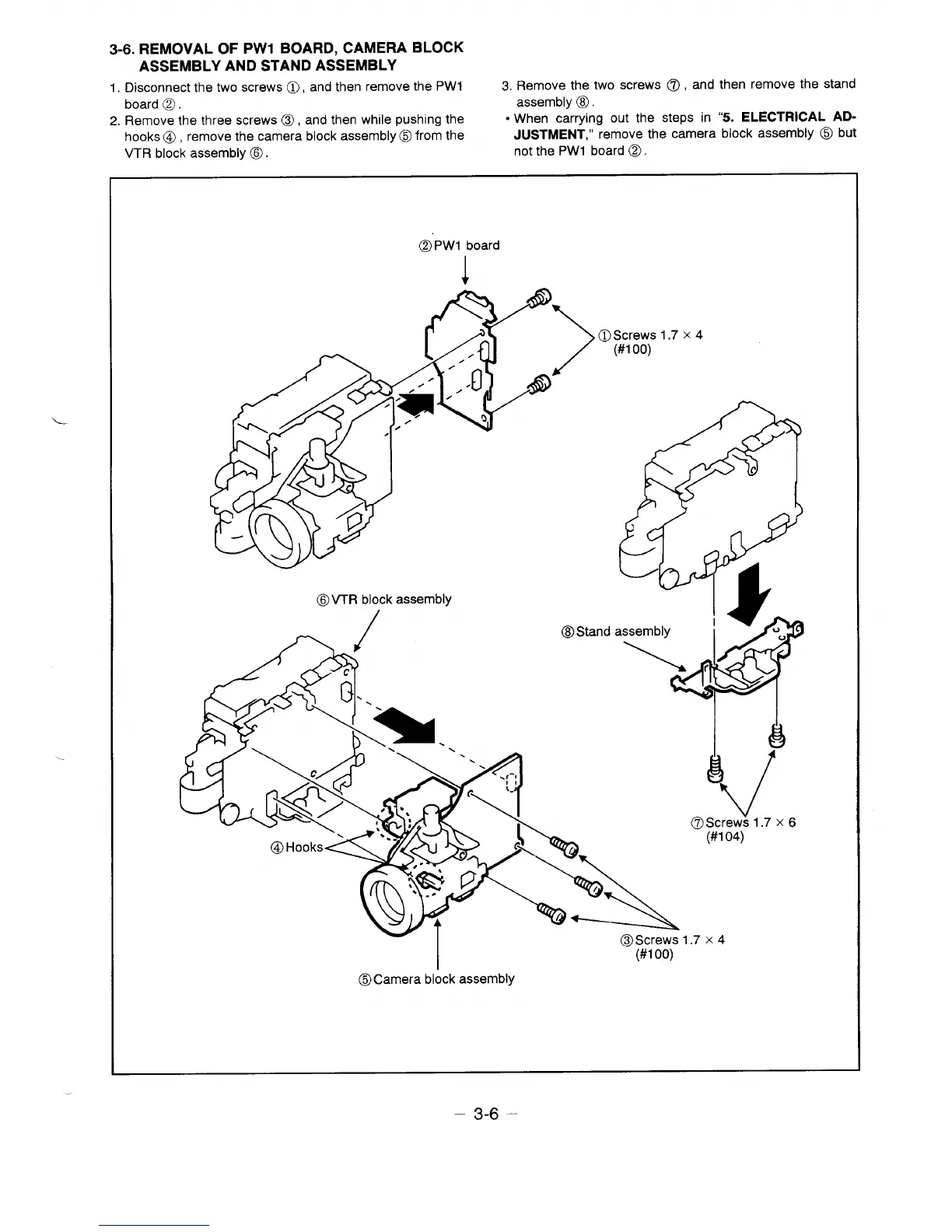
3-6. REMOVAL OF PW1 BOARD, CAMERA BLOCK
ASSEMBLY AND STAND ASSEMBLY
1.
Disconnect the two screws (i), and then remove the PW1
3. Remove the two screws 0, and then remove the stand
—
board Cl.
assembly o.
2. Remove the three screws o, and then while pushing the
● When carrying out the steps in “5. ELECTRICAL AD-
hooks o, remove the camera block assembly o from the
JUSTMENT,” remove the camera block assembly o but
VTR block assembly o.
not the PW1 board Q.
Q PW1 board
1
1.7X4
OVTR block assembly
4
d
8
(7)Screws 1.7 x 6
- (#1 04)
1.7X4
I
(#100)
6Camera block assembly
– 3-6-
 Loading...