2-4. SETUP FOR ADJUSTMENT
For adjustment of the VTR section, the video signal from
the pattern generator is used as the adjustment signal.
Therefore, it is necessary that this video output signal is
within the specified level.
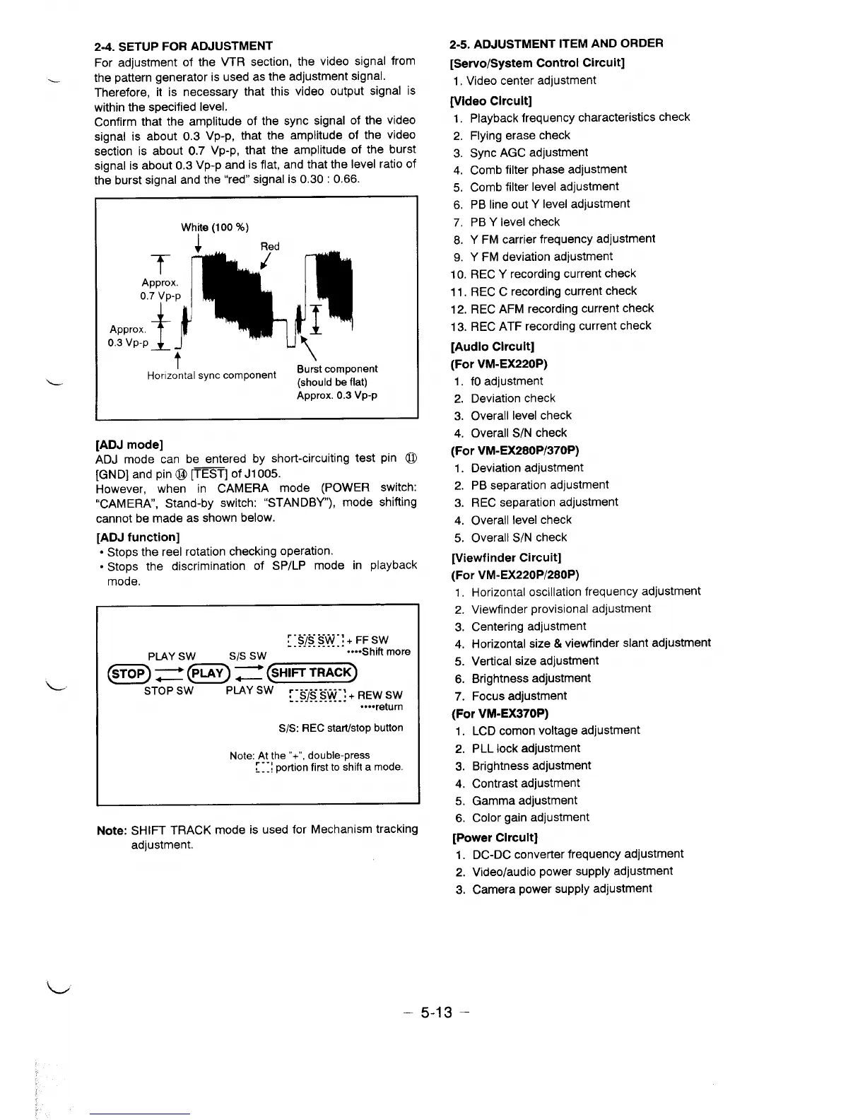
Confirm that the amplitude of the sync signal of the video
signal is about 0.3 Vp-p, that the amplitude of the video
section is about 0.7 Vp-p, that the amplitude of the burst
signal is about 0.3 Vp-p and is flat, and that the level ratio of
th~ burst signal and the “red” signal is 0.30:0.66.
1-
L
Wh~e (100%)
4
Red
T
Approx.
0.7 Vp-p
Approx.
0.3 Vp-p
t
Horizontal sync component
Burst component
(should be flat)
Approx. 0.3 Vp-p
[ADJ mode]
ADJ mode can be entered by short-circuiting test pin @
[GND] and pin@ [=] of J1005.
However, when in CAMERA mode (POWER switch:
“CAMERA, Stand-by switch: “STANDBY”), mode shifting
cannot be made as shown below.
[ADJ function]
● Stops the reel rotation checking operation.
● Stops the discrimination of SP/LP mode in playback
mode.
Y-sissw”:+wsw
............
PLAY Sw
Sls Sw
....Shift more
@@~~~@==~
STOP SW
PLAY SW :-s/s Sw ,+ REW Sw
. . . . . . .. .
. . . . . . . .. .. .
....return
S/S: REC start/stopbutton
Note: rA}he “+”,double-press
. . . . portion first to shift a mode
Note: SHIFT TRACK mode is used for Mechanism tracking
adjustment.
2-5. ADJUSTMENT ITEM AND ORDER
[Servo/System Control Circuit]
1. Video center adjustment
[Video Circuit]
1.
2.
3.
4.
5.
6.
7.
8.
9.
Playback frequency characteristics check
Flying erase check
Sync AGC adjustment
Comb filter phase adjustment
Comb filter level adjustment
PB line out Y level adjustment
PB Y level check
Y FM carrier frequency adjustment
Y FM deviation adjustment
10. REC Y recording current check
11. REC C recording current check
12. REC AFM recording current check
13. REC ATF recording current check
[Audio Circuit]
(For VM-EX220P)
1. fOadjustment
2. Deviation check
3. Overall level check
4. Overall S/N check
(For VM-EX280P/370P)
1.
2.
3.
4.
5.
Deviation adjustment
PB separation adjustment
REC separation adjustment
Overall level check
Overall S/N check
[Viewfinder Circuit]
(For VM-EX220P/280P)
1, Horizontal oscillation frequency adjustment
2. Viewfinder provisional adjustment
3. Centering adjustment
4. Horizontal size & viewfinder slant adjustment
5. Vertical size adjustment
6. Brightness adjustment
7. Focus adjustment
(For VM-EX370P)
1.
2.
3.
4.
5.
6.
LCD comon voltage adjustment
PLL lock adjustment
Brightness adjustment
Contrast adjustment
Gamma adjustment
Color gain adjustment
[Power Circuit]
1. DC-DC converter frequency adjustment
2. Video/audio power supply adjustment
3. Camera power supply adjustment
– 5-13 –
 Loading...