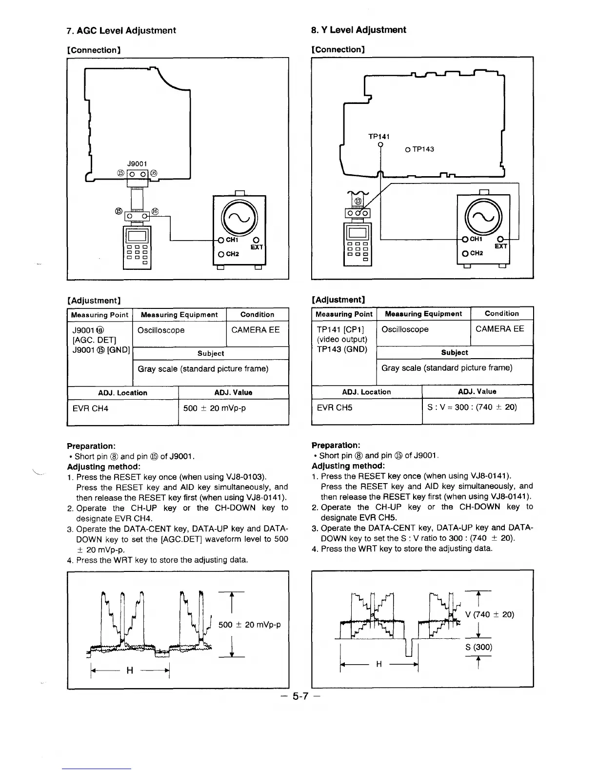
7. AGC Level Adjustment
[Connection]
8. Y Level Adjustment
rConnectionl
-—–— ——-
n
J9001
n
D
~o
CH1
0
nun
EXT
000
auu
0 CH2
a
i-l d
[Adjustment]
Measuring Point
Measuring Equipment
Condition
J9001 @
Oscilloscope
CAMERA EE
[AGC. DET]
J9001 @ [GND]
Subject
Gray scale (standard picture frame)
I
ADJ. Location I
ADJ. Value
EVR CH4
500 f 20 mVp-p
L
I
t
t
I
TP141
U=--l
I /
1
[Adjustment]
Measuring Point
Measuring Equipment
I
Condition
TP141 [CP1]
Oscilloscope
CAMERA EE
(video
OUtDUt)
TP143 (GNDj
I
t
Subiect
Gray scale (standard picture frame)
I
ADJ. Location
I
ADJ. Value
EVR CH5
S: V=300:(740t 20)
Preparation:
● Short pin B and pin o of J9001.
Adjusting method:
L-.
1. Press the RESET key once (when using VJ8-01 03).
Press the RESET key and AID key simultaneously, and
then release the RESET key first (when using VJ8-0141 ).
2. Operate the CH-UP key or the CH-DOWN key to
designate EVR CH4.
3. Operate the DATA-CENT key, DATA-UP key and DATA-
DOWN key to set the [AGC. DET] waveform level to 500
f Zr)mvp-p,
4. Press the WRT key to store the adjusting data
Preparation:
● Short pin 8 and pin o of J9001.
Adjusting method:
1. Press the RESET key once (when using VJ8-0141 ).
Press the RESET key and Al D key simultaneously, and
then release the RESET key first (when using VJ8-0141 ).
2. Operate the CH-UP key or the CH-DOWN key to
designate EVR CH5.
3. Operate the DATA-CENT key, DATA-UP key and DATA-
DOWN key to set the S : V ratio to 300: (740 f 20).
4. Press the WRT key to store the adjusting data.
T
500 t 20 mVp-p
L
t--” ---?
& B
I-4
T
v (740 t 20)
s (300)
T
—
5-7
 Loading...