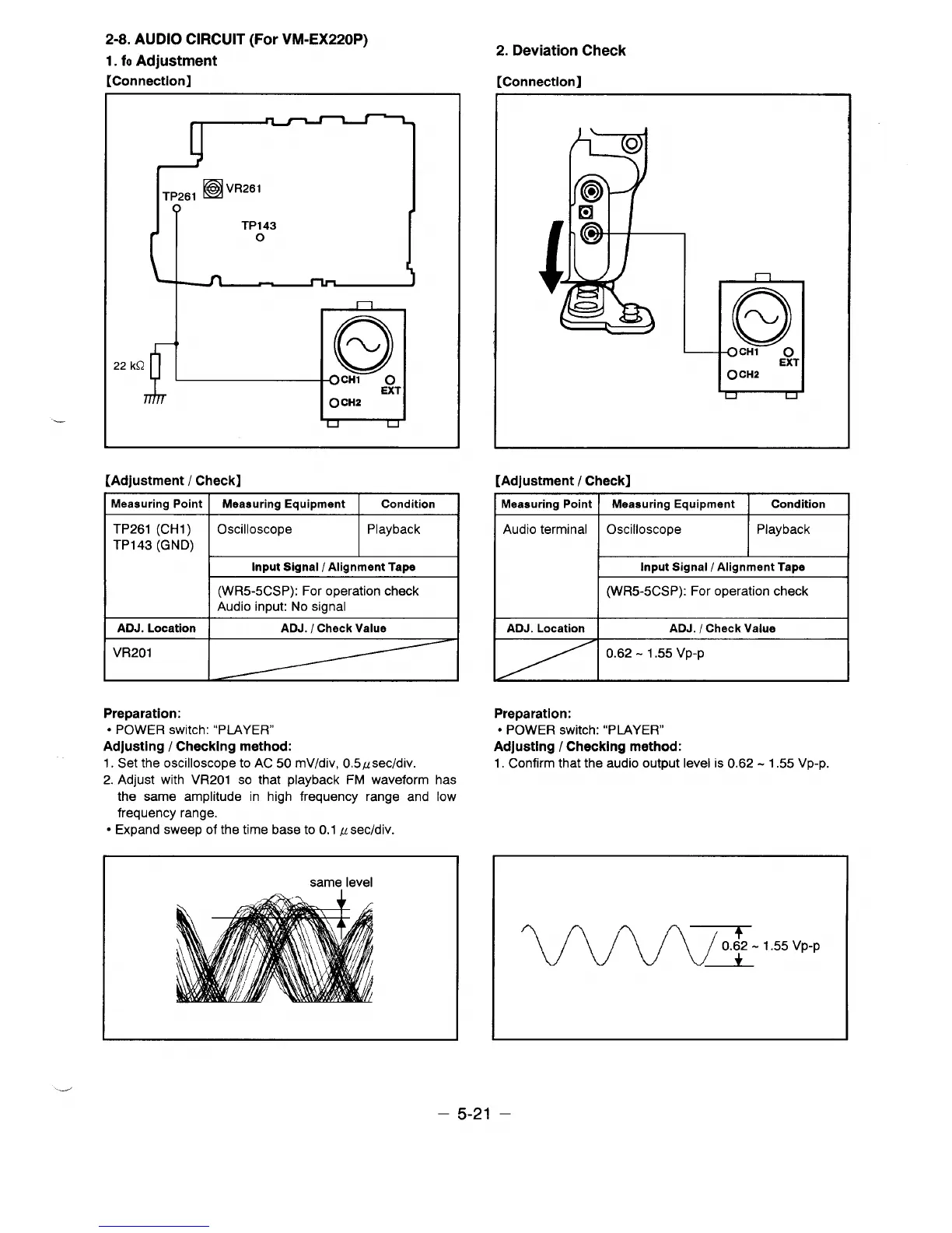
2-8. AUDIO CIRCUIT (For VM-EX220P)
1. fo Adjustment
[Connection]
L
h
~p,,,
❑ VR261
TP143
o
I
n
)
22 kQ
Q
CH1
o
EXT
O CH2
[Adjustment / Check]
Meaauring point I
Measuring Equipment
I
Condition
1
TP261 (CH1 )
TP143 (GND)
-
Input Signal / Alignment Tape
(WR5-5CSP): For operation check
Audio input: No signal
ADJ. Location
ADJ. / Check Value
VR201
Preparation:
● POWER switch: “PLAYER”
Adjusting / Checking method:
1. Set the oscilloscope to AC 50 mV/div, 0.5~sec/div.
2. Adjust with VR201 so that playback FM waveform has
the same amplitude in high frequency range and low
frequency range.
● Expand sweep of the time base to 0,1 ,usec/div.
I
same level
I
2. Deviation Check
[Connection]
n
,
0
OCH1 O
EX1
0CH2
u
d
[Adjustment / Check]
Measuring Point Meaauring Equipment
Condition
1
Audio terminal
Oscilloscope
Playback
I
I
Input Signal / Alignment Tape
%
(WR5-5CSP): For operation check
I
Preparation:
● POWER switch: “PLAYER”
Adjusting / Checking method:
1. Confirm that the audio output level is 0.62-1.55 VP-P.
WW3-155VP-P
.J
– 5-21 –
 Loading...