1-5. NOTES
1.
Perform the adjustment after aging for ten minutes or
L
more.
2. As a rule, perform the adjustment in the order as shown
in the section 1-8.
3. Set the line select switch of the vectorscope to +V.
1-6. STANDARD SEITING
1. Use the 5,100K viewer for a subject.
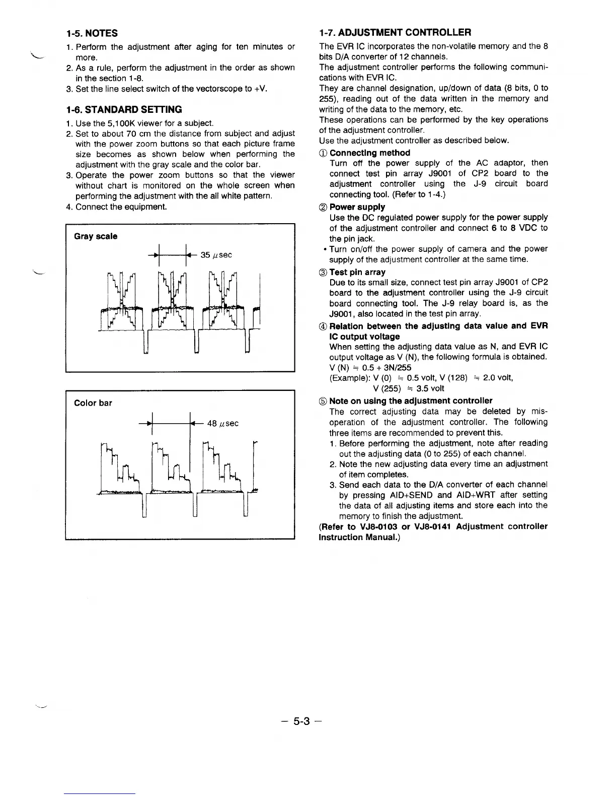
2. Set to about 70 cm the distance from subject and adjust
with the power zoom buttons so that each picture frame
size becomes as shown below when performing the
adjustment with the gray scale and the color bar.
3. Operate the power zoom buttons so that the viewer
without chart is monitored on the whole screen when
performing the adjustment with the all white pattern.
4. Connect the equipment.
L.
Gray scale
+-k3’”see
Color bar
1-7. ADJUSTMENT CONTROLLER
The EVR IC incorporates the non-volatile memory and the 8
bits D/A converter of 12 channels.
The adjustment controller performs the following communi-
cations with EVR IC.
They are channel designation, up/down of data (8 bits, O to
255), reading out of the data written in the memory and
writing of the data to the memory, etc.
These operations can be performed by the key operations
of the adjustment controller.
Use the adjustment controller as described below.
O Connecting method
Turn off the power supply of the AC adaptor, then
connect test pin array J9001 of CP2 board to the
adjustment controller using the J-9 circuit board
connecting tool. (Refer to 1-4.)
Q
Power supply
Use the DC regulated power supply for the power supply
of the adjustment controller and connect 6 to 8 VDC to
the pin jack.
● Turn on/off the power supply of camera and the power
supply of the adjustment controller at the same time.
o Test pin array
Due to its small size, connect test pin array J9001 of CP2
board to the adjustment controller using the J-9 circuit
board connecting tool. The J-9 relay board is, as the
J9001, also located in the test pin array.
Q Relation between the adjusting data value and EVR
IC output voltage
When setting the adjusting data value as N, and EVR IC
output voltage as V (N), the following formula is obtained.
V (N) = 0.5+ 3N/255
(Example): V (0) = 0.5 volt,V(128) = 2.0 volt,
V (255) = 3.5 volt
(Q Note on using the adjustment controller
The correct adjusting data may be deleted by mis-
operation of the adjustment controller. The following
three items are recommended to prevent this.
1. Before performing the adjustment, note after reading
out the adjusting data (Oto 255) of each channel.
2. Note the new adjusting data every time an adjustment
of item completes.
3. Send each data to the D/A converter of each channel
by pressing AID+SEND and AID+WRT after setting
the data of all adjusting items and store each into the
memory to finish the adjustment.
(Refer to VJ8-0103 or VJ8-0141 Adjustment controller
Instruction Manual.)
~---
– 5-3 –
 Loading...