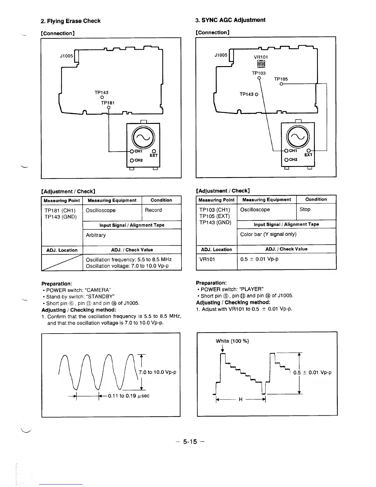
2. Flying Erase Check
rcrit-in~etlnnl
.-
-------------- *
J1OO5
(Ill
o
CH1
o
EXT
O CH2
L
[Adjustment / Check]
=
Input Signal / Alignment Tape
Arbitrary
ADJ. Location
ADJ. / Check Value
Oscillation frequency: 5.5 to 8.5 MHz
Oscillation voltage: 7.0 to 10.0 Vp-p
Preparation:
● POWER switch: “CAMERA”
● Stand-by switch: “STANDBY
“ Short pin @, pin 0 and pin@ of J1OO5.
Adjusting / Checking method:
1, Confirm that the oscillation frequency is 5.5 to 8.5 MHz,
3. SYNC AGC Adjustment
[Connection]
TP103
[Adjustment / Check]
Meaauring Point
Meaauring Equipment
Condition
,
1 i
TP103 (CH1) Oscilloscope
TP105 (EXT)
I stop
I
I
TP143 ~GND)
1
Input Signal / Alignment Tape
Color bar (Y signal only)
ADJ. Location
ADJ. / Check Value
VR101
0.5 * 0.01 Vp-p
Preparation:
● POWER switch: “PLAYER”
● Short pin @, pin@ and pin @ of J1OO5.
Adjusting / Checking method:
1. Adjust with VR101 to 0.5 t 0.01 Vp-p.
and that the oscillation voltage is 7.0 to 10.0 Vp-p.
White (100 %)
 Loading...