3-5. REMOVAL OF CABINET ASSEMBLY (LEIT)
AND VIEWFINDER
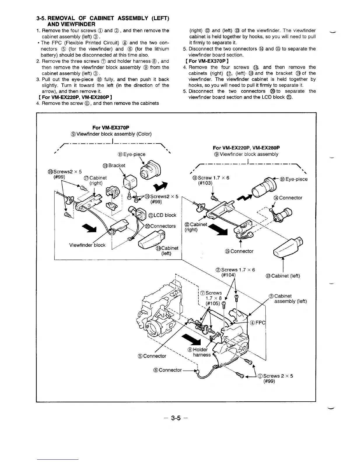
1.
Remove the four screws O and Q, and then remove the
cabinet assembly (left) o.
● The FPC (Flexible Printed Circuit) Q and the two con-
nectors o (for the viewfhder) and o (for the lithium
5.
battery) should be disconnected at this time also.
(right) (Q and (left) o of the viewfinder, The viewfinder _
cabinet is held together by hooks, so you will need to pull
it firmly to separate it.
Disconnect the two connectors (Q and o to separate the
viewfhder board section.
2, Remove the three screws Q) and holder harness o, and [ For VM-EX370P ]
then remove the viewfinder block assembly @ from the 4, Remove the four screws @, and then remove the
cabinet assembly (left) o. cabinets (right) ~, (left) o and the bracket o of the
3, Pull out the eye-piece (lJ fully, and then push it back vietitnder. The viewfinder cabinet is held together by
slightly. Turn it toward the left (in the direction of the hooks, so you will need to pull it firmly to separate it.
arrow), and then remove it. 5. Disconnect the two connectors o to separate the
[ For tiM-EX220P, vM-Ex280P ]
viewfinder board section and the LCD block @l.
4, Remove the screw@, and then remove the cabinets
@
For VM-EX370P
@viewfinder block assembly (Color)
,7-–-–-–-–-––
l_.–.–.–_.>
For VM-EX220P, VM-EX280P
/
@Eye-piece ‘~
QViewfinder block assembly
\
B.Screws 1.7 x 6
I
p., <
(#1
04)
oCabinet (left)
Cabinet
assembly
\AaScrews2x5
(#99)
(left)
—
– 3-5 –
 Loading...