Home
Siemens
Industrial PC
SIMATIC IPC477D
Siemens SIMATIC IPC477D User Manual
5
of 1
of 1 rating
292 pages
Give review
Manual
Specs
To Next Page
To Next Page
To Previous Page
To Previous Page
Loading...
Overview
1.2
Design of the built
-
in units
SIMATIC IPC477D, IPC477D PR
O
22
Operating Instructions, 11/2016, A
5E31347228-
AF
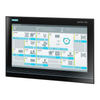
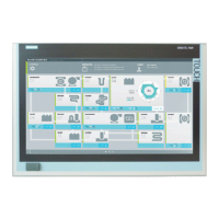
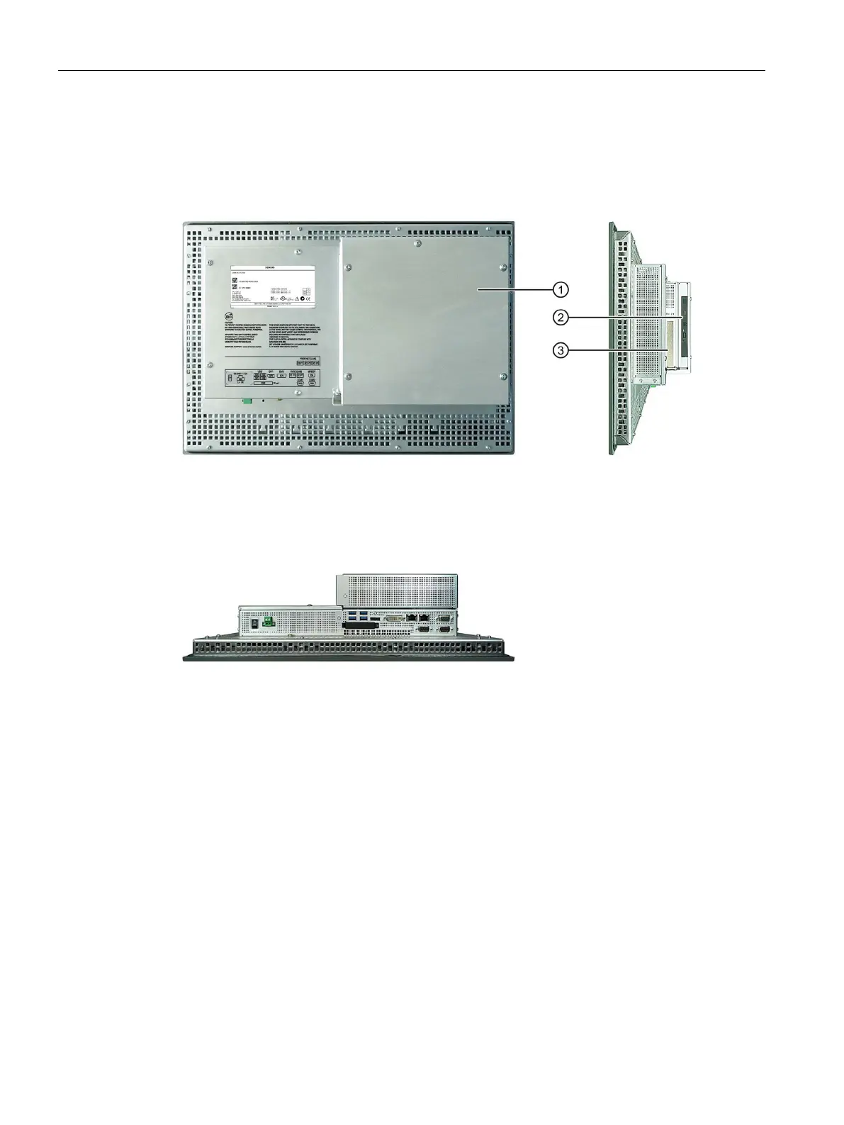
1.2.4.3
Devices with PCIe card and with DVD drive
The following fi
gures show the 15" devic
e with resistive singl
e
-
touch screen as an exam
ple.
Rear view and side view
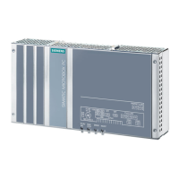
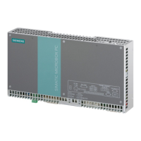
①
Rear panel
②
DVD drive
③
PCIe card
Bottom view
21
23
Table of Contents
Default Chapter
3
Preface
3
Table of Contents
5
1 Overview
11
Product Description
11
Design of the Built-In Units
15
Devices with Resistive Single Touch Screen
15
Devices with Capacitive Multi-Touch Screen
17
Touch/Key Devices with Resistive Single Touch Screen
18
Devices with Expansions
20
Devices with DVD Drive
20
Devices with Pcie Card
21
Devices with Pcie Card and with DVD Drive
22
Operator Controls or Touch/Key Devices with Resistive Single-Touch Screen
23
Interfaces and Operator Controls for Devices with 24 V DC Power Supply
24
Interfaces and Operator Controls for Devices with 240 V AC Power Supply
26
Design of the PRO Device
28
Interfaces and Operator Controls for PRO Device
31
Accessory Kit
32
Accessories
32
System Components for Built-In Units
34
System Components for PRO Devices
35
Base Adapter
35
Adapter Set for Support Arm and Stand Mounting of PRO Device
36
Round Tube Adapter
37
Extension Unit and Operator Controls
39
2 Safety Instructions
41
General Safety Instructions
41
Notes on Usage
44
3 Mounting and Connecting the Device
47
Preparing for Mounting
47
Checking the Delivery Package
47
Device Identification Data
49
Built-In Unit
51
Permitted Mounting Positions
51
Preparing the Mounting Cutout
53
Labeling the Function Keys
55
PRO Device
57
Permitted Mounting Positions
57
Installing the Built-In Unit
59
Installation Guidelines
59
Mounting Clips or Mounting Brackets, Position for IP65-Compliant Installation
61
Mounting the Device with Mounting Clips
63
Mounting the Device with Mounting Brackets
65
Position of the Mounting Clips for IP66-Complaint Installation
67
Mounting the PRO Device
68
Notes on Mounting
68
Prepared for Support Arm or Stand Without Extension Elements (Flange on Top)
70
Prepared for Support Arm and Extension Elements (Flange Mount)
74
Connecting the Device
78
Notes on Connecting
78
Power Supply Built-In Unit
80
Connecting the Protective Earth
80
Connect 100-240 VAC Power Supply
82
Connecting the Terminal
85
Connecting the 24 V DC Power Supply
86
Power Supply PRO Device
88
Opening and Closing the Terminal Compartment Cover
88
Connecting the PE Conductor
91
Connecting the 24 VDC Power Supply
92
Connecting Peripheral Equipment
94
Connecting the Device to Networks
95
Profinet
97
Securing Cables on the Built-In Unit
99
Attaching PROFINET Strain Relief
100
Securing Cables in the Built-In Unit with Atex/Iecex/Ul Hazloc Approval
101
Securing the Cables on the PRO Device
102
4 Commissioning the Device
103
General Information on Commissioning
103
Initial Commissioning
105
Windows Action Center
107
Notes on Various Device Configurations
108
SIMATIC IPC Wizard 2.1
108
System Requirements
108
Installing IPC Wizard
110
Notes on the DVD Burner
112
5 Operating the Device and Device Functions
113
Operator Input Options
113
Operating a Device with Resistive Single Touch Screen
114
Operating a Capacitive Multi-Touch Screen Device and PRO Device
115
Operating a Touch/Key Device
118
IPC Wizard Functions
121
Extended Device Functions
122
Monitoring Functions
122
Overview of the Monitoring Functions
122
Temperature Monitoring/Display
123
Watchdog (WD)
124
Battery Monitoring
125
Enhanced Write Filter
125
File Based Write Filter (FBWF)
128
Buffer Memory NVRAM
129
Active Management Technology (AMT)
130
Trusted Platform Modul (TPM)
132
6 Expanding the Device and Assigning Device Parameters
133
Opening the Device
133
Opening the Built-In Unit
133
Opening and Closing the Backplane Cover PRO Device
135
Installing and Removing a Memory Module
138
Removing a Pcie Card (Built-In Units with Pcie Card Without DVD Drive)
140
Removing a Pcie Card (Built-In Units with Pcie Card and DVD Drive)
142
Installing and Removing a DVD Drive (Built-In Unit Only)
142
Installing and Removing a Cfast Card
144
Installing and Removing a Cfast Card (External Slot)
144
Installing and Removing a Cfast Card (Internal Slot)
146
7 Maintaining and Servicing Your Device
149
Maintenance
149
Repair Information
150
Cleaning the Device Front
153
Installing and Removing Hardware
154
Built-In Unit
154
Replacing Back-Up Battery (Device with 12" Display)
154
Replacing Back-Up Battery (Devices with 15", 19" or 22" Display)
155
Replacing SSD (Device with 12" Display)
156
Replacing the SSD (Devices with 15", 19" or 22" Display)
158
Replacing HDD
160
PRO Device
161
Replacing the Backup Battery (PRO Device)
161
Replacing the SSD (PRO Device)
162
Installing the Software
164
Reinstalling the Operating System
164
General Installation Procedure
164
Restoring the Factory State of the Software Using the Restore DVD
165
Windows 7
167
Windows Embedded Standard
171
Partitioning Data Media
173
Partitioning in Windows Embedded Standard 7
173
Partitioning in Windows 7 Ultimate
174
Adapting Partitions in Windows 7 Ultimate and Windows Embedded Standard 7
174
Installing Drivers and Software
176
Update Installation
177
Updating the Operating System
177
Installing or Updating Application Programs and Drivers
177
CP 1616 Onboard
177
Backing up Data
178
Recycling and Disposal
178
8 Technical Information
179
Certificates and Approvals
179
Directives and Declarations
184
Electromagnetic Compatibility
184
ESD Guideline
185
Dimension Drawings
188
Dimension Drawing of 15" Device with Capacitive Multi-Touch Screen
188
Dimension Drawing of 19" Device with Capacitive Multi-Touch Screen
190
Dimension Drawing of 22" Device with Capacitive Multi-Touch Screen
191
Dimension Drawing 15" PRO Device with Capacitive Multi-Touch Screen
192
Dimension Drawing 19" PRO Device with Capacitive Multi-Touch Screen
196
Dimension Drawing 22" PRO Device with Capacitive Multi-Touch Screen
199
Dimension Drawing of 12" Device with Resistive Single-Touch Screen
202
Dimension Drawing of 15" Device with Resistive Single-Touch Screen
203
Dimension Drawing of 19" Device with Resistive Single-Touch Screen
204
Dimension Drawing of 22" Device with Resistive Single-Touch Screen
205
Dimension Drawing of 15" Touch/Key Device with Resistive Single-Touch Screen
206
Dimension Drawing of Labeling Strips
207
Technical Specifications
208
Built-In Unit
208
General Technical Specifications
208
Environmental Conditions
213
PRO Device
217
General Specifications PRO Device
217
Ambient Conditions PRO Device
222
Information on Insulation Tests, Protection Class and Degree of Protection
223
Rated Voltages
223
Power Requirements of the Components
224
Integrated DC Power Supply
224
Alternating Voltage Supply PRO Device (AC)
225
Hardware Descriptions
226
External Ports
226
Com1/Com2
226
Cfast
227
Displayport
228
DVI-I
229
Ethernet
230
USB 3.0 Port
230
Usb 2.0
231
Profibus
231
Profinet
232
Internal Ports
233
Pcie Card
233
System Resources
235
Currently Allocated System Resources
235
Assignment of System Resources
235
I/O Address Areas
237
Overview of the Internal Module Registers
237
Watchdog Trigger Register (Read Only, Address 066H)
237
Watchdog Enable Register / 066H Select Register (Read/Write, Address 062H)
237
Battery Status Register (Read-Only, Address 50Ch)
239
NVRAM Address Register
239
CP 1616 Onboard Communications Processor
240
Introduction
240
Firmware Loader
242
Further Actions in STEP 7/NCM PC
244
BIOS Description
245
Overview
245
Opening the BIOS Selection Menu
246
Structure of the BIOS Setup Menu
248
Exit Menu
250
BIOS Setup Settings
251
BIOS Update
254
Alarm, Error and System Messages
256
Active Management Technology (AMT)
257
Introduction
257
Overview of AMT
258
Enabling Intel® AMT / Basic Configuration
258
Resetting the Intel® AMT to the Default Settings and Disabling AMT
260
Determining the Network Address
260
Forcing User Consent
261
Functional Scope in Windows
262
Windows Embedded Standard 7
262
Technical Support
265
Service and Support
265
Problem Solving
266
A.2 Problem Solving
266
Notes on the Use of Third-Party Modules
268
Markings and Symbols
269
Overview
269
Safety
269
Operator Controls
269
B.1 Overview
269
Certificates, Approvals and Markings
270
Interfaces
271
B.5 Interfaces
271
List of Abbreviations
273
Glossary
279
Index
287
Other manuals for Siemens SIMATIC IPC477D
Operating Manual
54 pages
5
Based on 1 rating
Ask a question
Give review
Questions and Answers:
Need help?
Do you have a question about the Siemens SIMATIC IPC477D and is the answer not in the manual?
Ask a question
Siemens SIMATIC IPC477D Specifications
General
Brand
Siemens
Model
SIMATIC IPC477D
Category
Industrial PC
Language
English
Related product manuals
Siemens SIMATIC IPC477E
188 pages
Siemens SIMATIC IPC477E PRO
178 pages
Siemens SIMATIC IPC427E
164 pages
Siemens SIMATIC IPC427C
170 pages
Siemens SIMATIC IPC427D
200 pages
Siemens SIMATIC IPC
22 pages
Siemens SIMATIC IPC377E
124 pages
Siemens SIMATIC IPC677E
158 pages
Siemens simatic ipc227e
156 pages
Siemens SIMATIC IPC627E
164 pages
Siemens SIMATIC IPC127E
100 pages
Siemens SIMATIC IPC647E
200 pages
 Loading...