4
Creating a ShopTurn Program 08/2005
4.1 Pro
ram structure
4
♥ Siemens AG, 2005. All rights reserved
4-124 SINUMERIK 840D sl Operation/Programming ShopTurn (BAT) – 08/2005 Edition
4.1 Program structure
A sequential control program is divided into three sub-areas:
Program header
Program blocks
End of program
These sub-areas form a machining plan.
Program
header
Program
end
Program
blocks
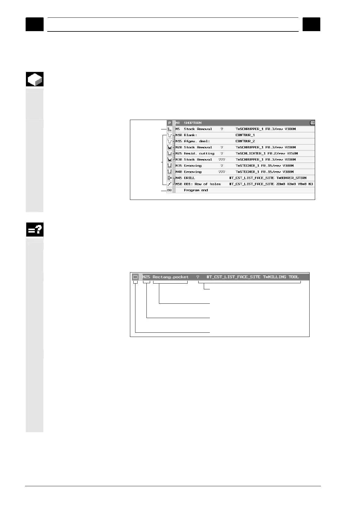
Program structure
Program header
The program header contains parameters that affect the entire
program, such as blank dimensions or retraction planes.
Program blocks
You determine the individual machining steps in the program blocks.
In doing this, you specify the technology data and positions, among
other things.
Technology data and
positions
Plain text, e.g. type
of machining
Block number allocated
by control
Symbol of machining cycle
Program block
Linked program blocks
For the "Contour turning", "Contour milling", "Milling", and "Drilling"
functions, program the technology blocks and contours or positioning
blocks separately. These program blocks are automatically linked by
the controller and connected by brackets in the work plan.
In the technology blocks, specify how and in what form the machining
should take place, e.g. centering first, and then drilling. In the
positioning blocks, determine the positions for the drilling or milling
machining, e.g. position the drill-holes in a full circle on the front
surface.

 Loading...


