5
ShopTurn Functions 08/2005
5.6 Contour millin
5
♥ Siemens AG, 2005. All rights reserved
5-310 SINUMERIK 840D sl Operation/Programming ShopTurn (BAT) – 08/2005 Edition
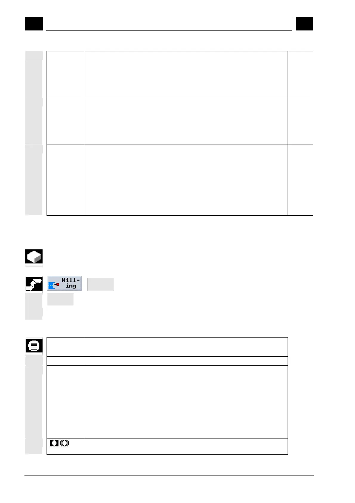
CP
Z0
Z1
DZ
UXY
End face Y:
Reference point
Reference point in Z direction (abs.)
Depth with reference to Z0 (abs. or inc.)
Maximum depth infeed (Z direction)
Finishing allowance in plane
Degrees
mm
mm
mm
mm
C0
X0
X1
DX
UYZ
Peripheral surface Y:
Reference point
Reference point in X direction (abs.)
Depth with reference to X0 (abs. or inc.)
Maximum depth infeed (X direction)
Finishing allowance in plane
Degrees
mm
mm
mm
mm
Retraction
mode
If more than one approach point is necessary, specify the retraction height to which
the tool retracts between approach points.
To retraction plane
Z0+safety clearance (for end face/end face C and end face Y only) or
X0+safety clearance (for peripheral surface/peripheral surface C and peripheral
surface Y only)
If there are no spigots or other elements in the machining range higher than Z0 (X0),
Z0 + safety clearance (X0 + safety clearance) can be programmed as the retraction
mode.
5.6.14 Chamfering a contour spigot
If you have planned edge breaking, mill a chamfer after that.
Contour
milling >
Spigot
milling
¾ Press the "Milling", "Contour milling" and "Spigot milling" soft keys.
¾ Select "Chamfer" machining mode.
Parameters Description of finishing the edge
T, D, F, S, V See Sec. "Creating program blocks".
Position Select from 8 different positions:
End face/End face C – Front
End face/End face C – Rear
Peripheral surface/Peripheral surface C – Inner
Peripheral surface/Peripheral surface C – Outer
End face Y – Front (only when Y axis exists)
End face Y – Rear (only when Y axis exists)
Peripheral surface Y – inner (only when Y axis exists)
Peripheral surface Y – Rear (only when Y axis exists)
Clamp/release spindle (for End face Y/Peripheral surface Y only)
The function must be set up by the machine manufacturer.

 Loading...


