Installation and Commissioning
8-137SJ62 Manual
C53000-G1140-C121-1
Jumpers X5 through X10 must be set on the same position!
Jumpers X5 through X10 must be set on the same position!
The jumpers are set at the factory based on the configuration ordered.
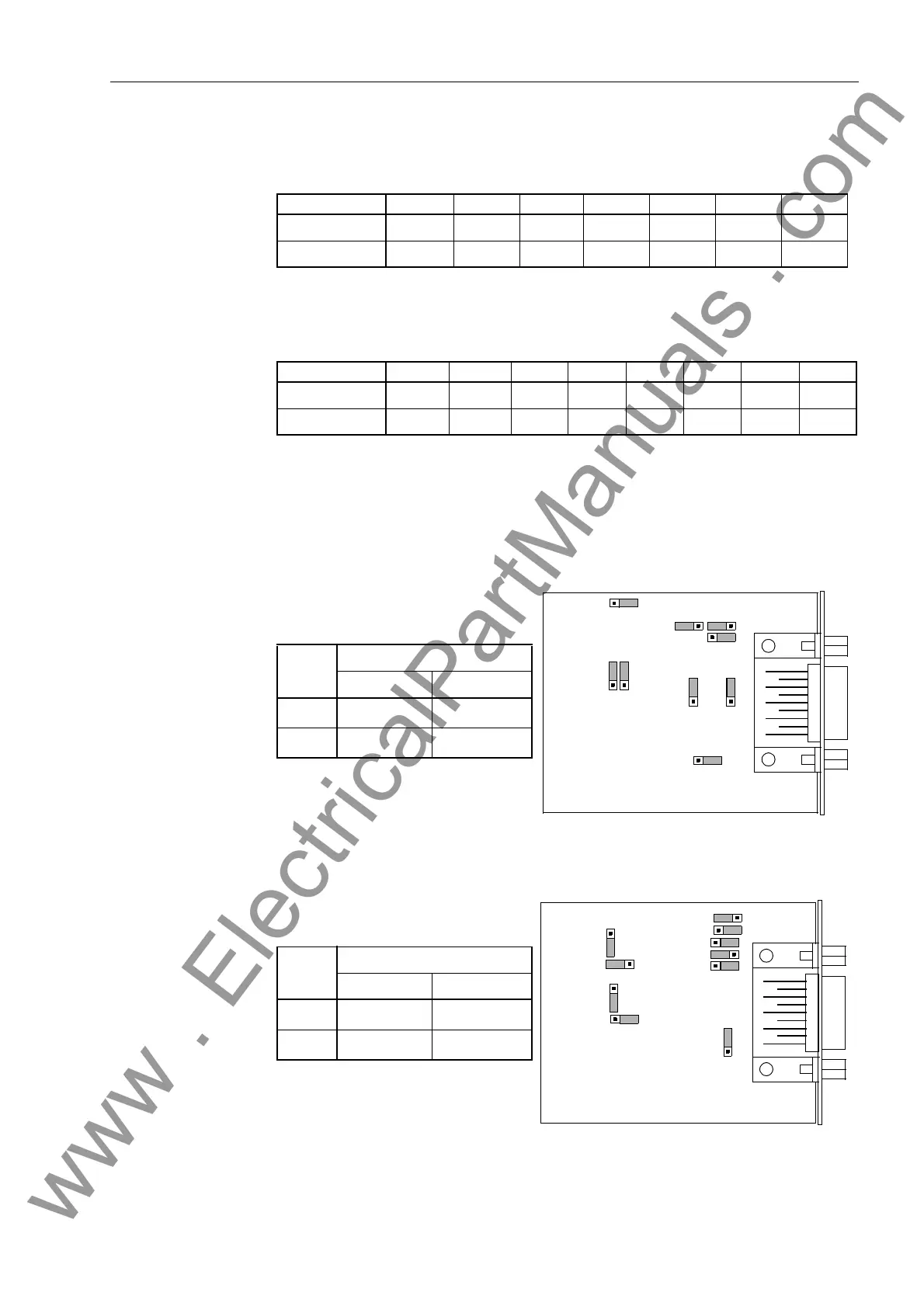
Jumpers X3 and X4 for bus termination of an RS 485 interface are also shown in Fig-
ure 8-7 and Figure 8-8.
Figure 8-7 Location of the Jumpers for Configuring the Terminating Resistors of the Inter-
face on Card Version C53207-A322-B80
Figure 8-8 Location of the Jumpers for Configuring the Terminating Resistors of the Inter-
face on Card Version C53207-A324-B180
Table 8-5 Configuration of Jumpers for RS 232 or RS 485 on the Interface Card (Circuit
Board Number C53207-A322-B80, Figure 8-7)
Jumper X5 X6 X7 X8 X9 X10 X11
RS 232 1–2 1–2 1–2 1–2 1–2 1–2 2–3
RS 485 2–3 2–3 2–3 2–3 2–3 2–3 2–3
Table 8-6 Configuration of Jumpers for RS 232 or RS 485 on the Interface Card (Circuit
Board Number C53207-A324-B180, Figure 8-8)
Jumper X5 X6 X7 X8 X10 X11 X12 X13
RS 232 1–2 1–2 1–2 1–2 1–2 2–3 1–2 1–2
RS 485 2–3 2–3 2–3 2–3 2–3 2–3 1–2 1–2
C53207-A322
-B80-03
X8
132
X3
132
X4
132
X6
132
X10
1
3
2
X11
1
3
2
X7
1
3
2
X9
1
3
2
X5
132
Jumper
Terminating Resistors
Connected Disconnected
X3 2-3
1-2
*
)
X4 2-3
1-2
*
)
*
) Factory Set
X3
132
X10
132
8X
1
3
2
X12
132
C53207-
A324-B180
1
3
2
X11
X6
X7
X4
X5
132
1
3
2
X13
Jumper
Terminating Resistors
Connected Disconnected
X3 2-3
1-2
*
)
X4 2-3
1-2
*
)
*
) Factory Set
www . ElectricalPartManuals . com
 Loading...


