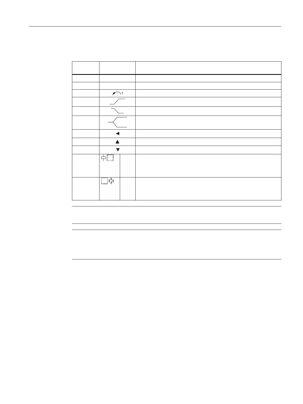
The following statuses and line faults are indicated as a diagnostics message with ashing
symbols:
Display
area
Symbol Meaning
① 200V Measured voltage is displayed
① Lx Flashing: Phase failure detected
① Flashing: Incorrect phase sequence detected
② Monitoring for voltage overshoot
② Monitoring for voltage undershoot
② Range monitoring (monitoring for voltage overshoot and undershoot)
② Voltage is in correct range
② A voltage overshoot has occurred
② A voltage undershoot has occurred
③ U▼
• Not ashing: Relay contact 11/12 open, relay contact 11/14 closed
• Flashing: Delay time (tripping delay) is running
• Masked out: Relay contact 11/12 closed, relay contact 11/14 open
③ U▲
• Not ashing: Relay contact 21/22 open, relay contact 21/24 closed
• Flashing: Delay time (tripping delay) is running
• Masked out: Relay contact 21/22 closed, relay contact 21/24 open
Note
On phase failure or phase sequence error, both CO contacts respond.
Note
If the monitoring relays are used downstream of a frequency converter, it is necessary to obtain
a waveform without additional zero crossings of the voltage. This can be achieved with the help
of a sine-wave lter.
You will nd more information about the switching behavior of the output relays in Chapter
"Functions (Page 105)".
6.6.4.2 Reset
RESET
How the outputs are reset depends on the "Reset response" parameter (see Chapter "Reset
response (Page 281)").
3UG4.1 line monitoring relay
6.6 3UG4615 / 3UG4616 line monitoring relays
SIRIUS 3UG4 / 3RR2 monitoring relay
Equipment Manual, 07/2021, NEB927043002000/RS-AD/005 109
 Loading...