12.6 Circuit diagrams
12.6.1 Internal circuit diagrams
Internal circuit diagrams 3UG4651 speed monitoring relay
U
AC/DC
AC/DC
A1 (+) EN RES 24V IN1
IN2 8V2
+ –
0V
pnp
A2 (–)
3UG46 51
11
12 14
– +
USP!
NAMUR
3UG4651‑.AA30 24 V AC/DC
3UG4651‑.AW30 24 to 240 V AC/DC
Note
On the 24 V AC/DC versions of the 3UG4651‑.AA30, terminals A1 / A2 and 0V / 24V are
electrically connected in the device!
On the 24 to 240 V AC / DC versions of the 3UG4651‑.AW30, terminals A1 / A2 and 0V / 24V are
electrically separated!
12.6.2 Wiring examples
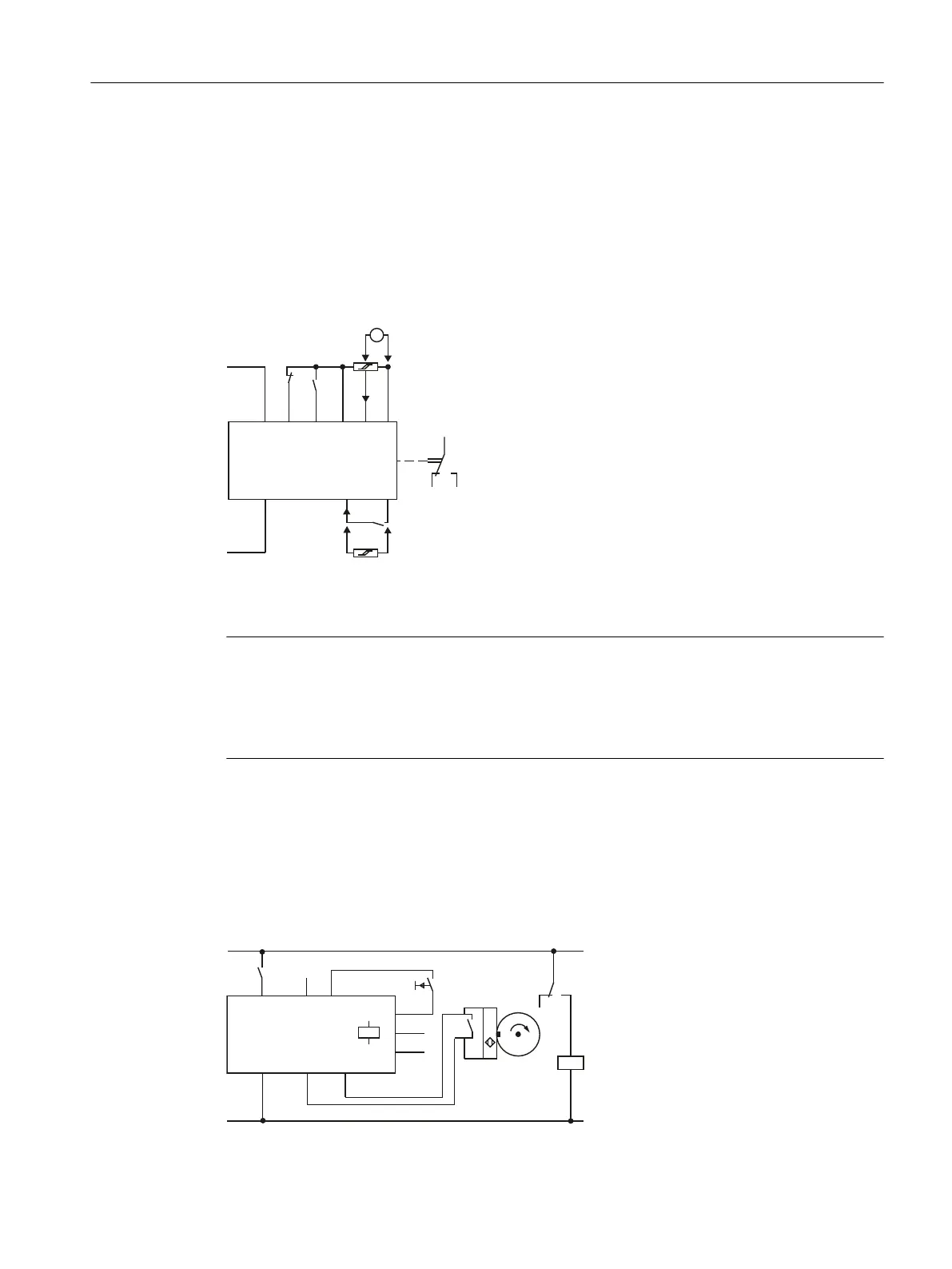
Speed monitoring relays without Enable input
AC/+U
S1
A2 (–)
IN2 8V2
RESEN
A1 (+)
24V BN
I
BU
NO
AC/0V
12 14
11
K1
K2
IN1
0V
3UG46 51
K1
NAMUR
Reset
USP!
3UG4651 speed monitoring relay
12.6 Circuit diagrams
SIRIUS 3UG4 / 3RR2 monitoring relay
Equipment Manual, 07/2021, NEB927043002000/RS-AD/005 237
 Loading...