12.2 Operator controls and connection terminals
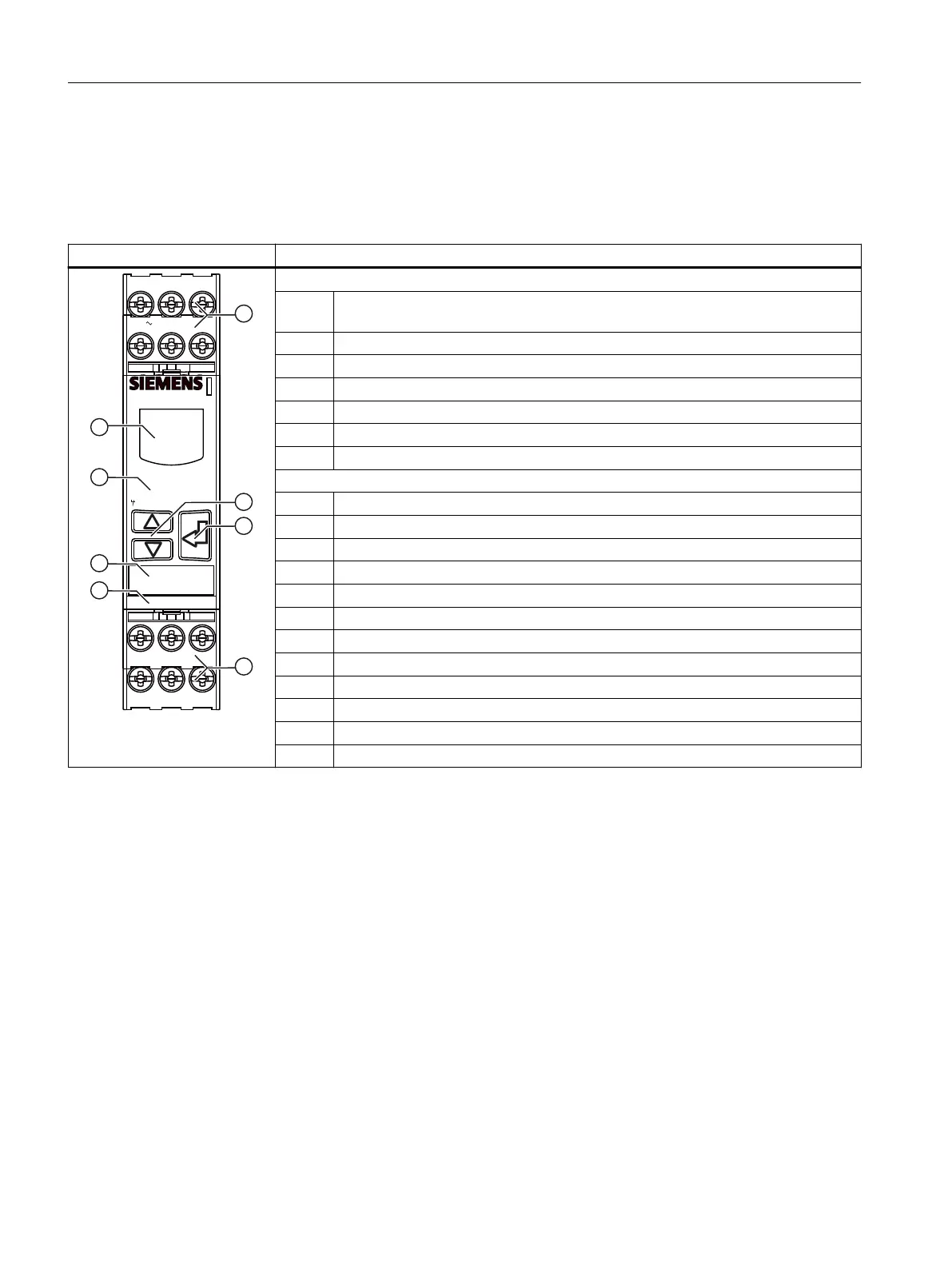
Front view / terminal labeling 3UG4651
Front view Description
EN RES
A1+
24V
14
1112
8V2
A2-
IN2
3UG4651-.....
SIRIUS
IN124V 0V
rpm -> Revolutions/min
Scale -> Pulses/revolution
onDel -> Power on delay
Mem ? -> Memory?
NC -> Circuit principle
Position digits
① Terminal block (removable):
Connection is possible using screw terminals or spring-loaded terminals.
② Arrow keys for menu navigation
③ SET key for menu navigation
④ Device article number
⑤ Label
⑥ Legend for menu
⑦ Display for parameterization, actual-value indication, and diagnostics
Terminal labels
A1+ Rated control supply voltage ∼ / +
A2- Rated control supply voltage ∼ / -
24V Supply voltage for pulse input IN1 (24 V / max. 50 mA)
IN1 Pulse input for pnp‑switching three-wire sensor (for 0 V DC/ +24 V pulses)
0V Supply voltage for pulse input IN1 (0 V / max. 50 mA)
EN Enable
RES Reset
IN2 Pulse input for two-wire NAMUR sensor or mechanical contact
8V2 Supply voltage for pulse input IN2
12 Output relay K1 CO contact NC contact
11 Output relay K1 CO contact root
14 Output relay K1 CO contact NO contact
You can nd additional information on the connection terminals and the permissible conductor
cross-sections in the Chapter "Connection methods (Page 23)".
You can nd information on connecting in the Chapter "Circuit diagrams (Page 237)".
3UG4651 speed monitoring relay
12.2 Operator controls and connection terminals
SIRIUS 3UG4 / 3RR2 monitoring relay
230 Equipment Manual, 07/2021, NEB927043002000/RS-AD/005
 Loading...