4.4.2 Function
General functionality
Depending on the setting, the current monitoring relays monitor an AC load current that ows
through terminals 1/L1 - 2/T1 and 3/L2 - 4/T2 of the device for overshoot (I▲) or undershoot (I▼)
or in range monitoring (I▲ and I▼ ≠ OFF).
Depending on their design, the current monitoring relays are powered with a 24 V AC/DC or
24 to 240 V AC/DC supply voltage through terminals B1/B2.
With two-phase apparent current monitoring, one changeover output, and analog adjustment,
the 3RR214.‑.A.30 (basic‑version) current monitoring relays provide a high level of monitoring
reliability particularly in the rated and overload ranges.
The switching states of the output relay are given below in the section entitled "Function
diagrams."
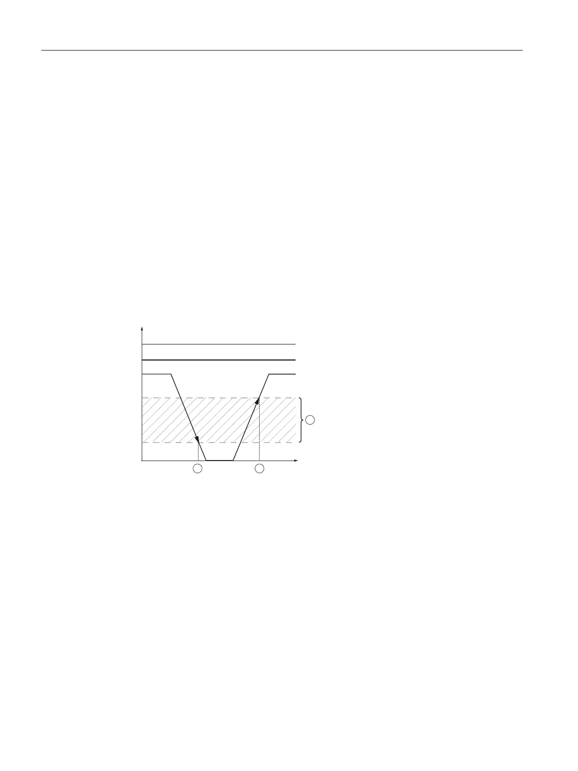
Cable break detected
① Cable break detected
② No cable break
③ Hysteresis cable break:
- S00: 1.2 A to 1.6 A
- S0: 3.0 A to 4.0 A
- S2: 6.0 A to 8.0 A
Figure 4-1 Diagram of cable break
If a cable break (zero current in branch circuit 1/L1 - 2/T1 or 3/L2 - 4/T2) is detected (time ①), all
running delay times are aborted, the red FAULT LED ashes rapidly and the CO contact
immediately changes its switching state.
When a dened current ow returns to both branch circuits (1/L1 - 2/T1, 3/L2 - 4/T2) (time ②),
the CO contact responds according to the dened settings.
If Memory = I, the tripping state is saved.
If the unmonitored phase 5/L3 - 6/T3 fails, this can be detected if a motor is connected by an
increase in current in both phases 1/L1 - 2/T1 and 3/L2 - 4/T2.
3RR2 current monitoring relays
4.4 3RR21 current monitoring relays
SIRIUS 3UG4 / 3RR2 monitoring relay
56 Equipment Manual, 07/2021, NEB927043002000/RS-AD/005
 Loading...