6.2 3UG4511 line monitoring relay
6.2.1 Operator controls and connection terminals
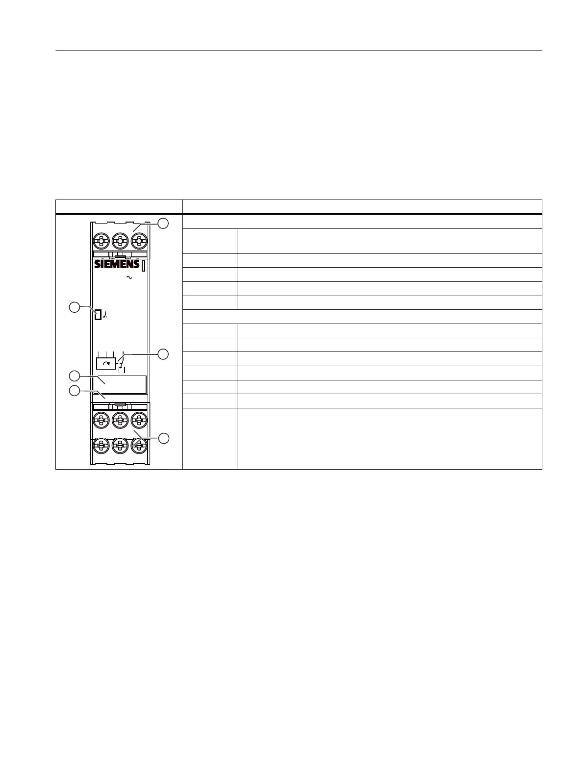
Front view / terminal labeling 3UG4511
Front view Description
12
14
11
L3
L2
L1
3UG4511-.....
SIRIUS
3 160-260V
L1
L2 L3
11
12 14
24
2122
Position digits
① Terminal block (removable)
Connection is possible using screw-type terminals or spring-loaded terminals.
② Circuit diagram
③ Device article number
④ Label
⑤ Status display: LED contact symbol (green)
Terminal labels
L1, L2, L3 Rated control supply voltage
12 Output relay K1 CO contact NC contact
11 Output relay K1 CO contact root
14 Output relay K1 CO contact NO contact
22 Output relay K2 CO contact NC contact (on the 3UG4511‑.B only)
21 Output relay K2 CO contact root (on the 3UG4511‑.B only)
24 Output relay K2 CO contact NC contact (on the 3UG4511‑.B only)
You can nd additional information on the connection terminals and the permissible conductor
cross-sections in the Chapter "Connection methods (Page 23)".
You can nd information on connecting in the Chapter "Circuit diagrams (Page 85)".
6.2.2 Function
General functionality
The 3UG4511 line monitoring relays monitor the phase sequence in a three-phase system.
The devices are self-powered (measuring voltage = rated control supply voltage) and work on
the closed-circuit principle. Depending on the version, the line monitoring relays are powered
with a rated control supply voltage of 160 V to 260 V (3UG4511‑..N20), 320 to 500 V
(3UG4511‑..P20) and 420 to 690 V (3UG4511‑..Q20) through terminals L1 / L2 / L3.
3UG4.1 line monitoring relay
6.2 3UG4511 line monitoring relay
SIRIUS 3UG4 / 3RR2 monitoring relay
Equipment Manual, 07/2021, NEB927043002000/RS-AD/005 83
 Loading...