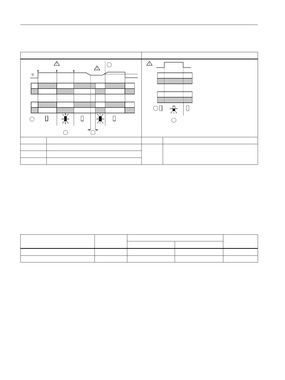
Function diagrams 3UG4513
Phase failure and undervoltage Incorrect phase sequence
11/14
-20 %
L1-L2-L3L2-L3L1-L2-L3
n
3~
5 %
11/12
21/24
21/22
1
2
3
4
OFF
OFF OFFON ON
LED
11/14
11/12
21/24
21/22
L3-L2-L1
1
2
FLASH OFFOFF
LED
① LED phase failure / phase sequence: Red ① LED phase failure / phase sequence: Red
② Phase failure ② Phase sequence
③ Tripping delay time
④ Hysteresis
6.4.3 Operation
Parameters
The following parameters can be set on the relevant rotary button using a screwdriver:
Table 6-2 Parameter information, 3UG4513 line monitoring relay
Parameters Control ele‐
ment
1)
Setting range Increment
Minimum value Maximum value
Tripping delay time (Delay) 3 0.1 s 20 s Continuous
Nominal line voltage (3~U
n
) 2 200 V 690 V
2)
Continuous
1)
The position digits refer to the front view in Chapter "Operator controls and connection
terminals (Page 92)."
2)
absolute threshold
The parameters are described in Chapter "Parameters (Page 281)."
Required tools
The same screwdriver can be used to set the parameters as for mounting the line monitoring
relays.
3UG4.1 line monitoring relay
6.4 3UG4513 line monitoring relay
SIRIUS 3UG4 / 3RR2 monitoring relay
94 Equipment Manual, 07/2021, NEB927043002000/RS-AD/005
 Loading...