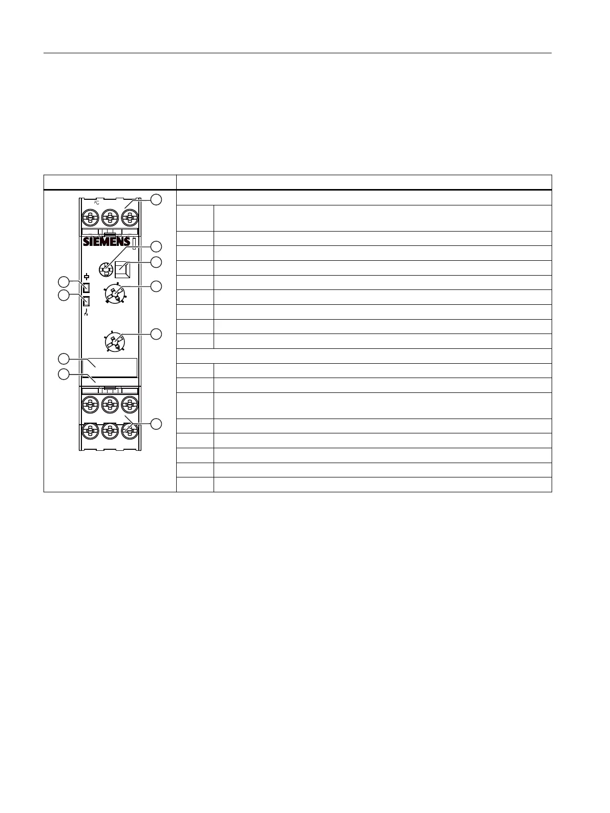
5.2 Operator controls and connection terminals
Front view / terminal labeling
Front view Description
14
1112
Min
A2-
Max
M
A1+
3UG4501-.....
SIRIUS
UN
R sens
2
10s
0,5
Delay
10
30
3
100
200kΩ
5
7
24V
Position digits
① Terminal block (removable):
Connection is possible using screw terminals or spring-loaded terminals.
② Rotary button for setting the monitoring mode.
③ Display eld: drainage control (OV) or inow control (UN)
④ Rotary button for setting the sensor sensitivity (R sens)
⑤ Rotary button for setting the tripping delay (Delay)
⑥ Device article number
⑦ Label
⑧ Status display: LED contact symbol (yellow)
⑨ Status display: LED coil symbol (green)
Terminal labels
A1+ Rated control supply voltage ∼ / +
A2- Rated control supply voltage ∼ / -
M
(GND)
Reference point
Min Minimum level
Max Maximum level
12 Output relay K1 CO contact NC contact
11 Output relay K1 CO contact root
14 Output relay K1 CO contact NO contact
You can nd additional information on the connection terminals and the permissible conductor
cross-sections in the Chapter "Connection methods (Page 23)".
You can nd information on connecting in the Chapter "Circuit diagrams (Page 78)".
3UG4501 lling level monitoring relay
5.2 Operator controls and connection terminals
SIRIUS 3UG4 / 3RR2 monitoring relay
72 Equipment Manual, 07/2021, NEB927043002000/RS-AD/005
 Loading...