4.4 3RR21 current monitoring relays
4.4.1 Operator controls and connection terminals
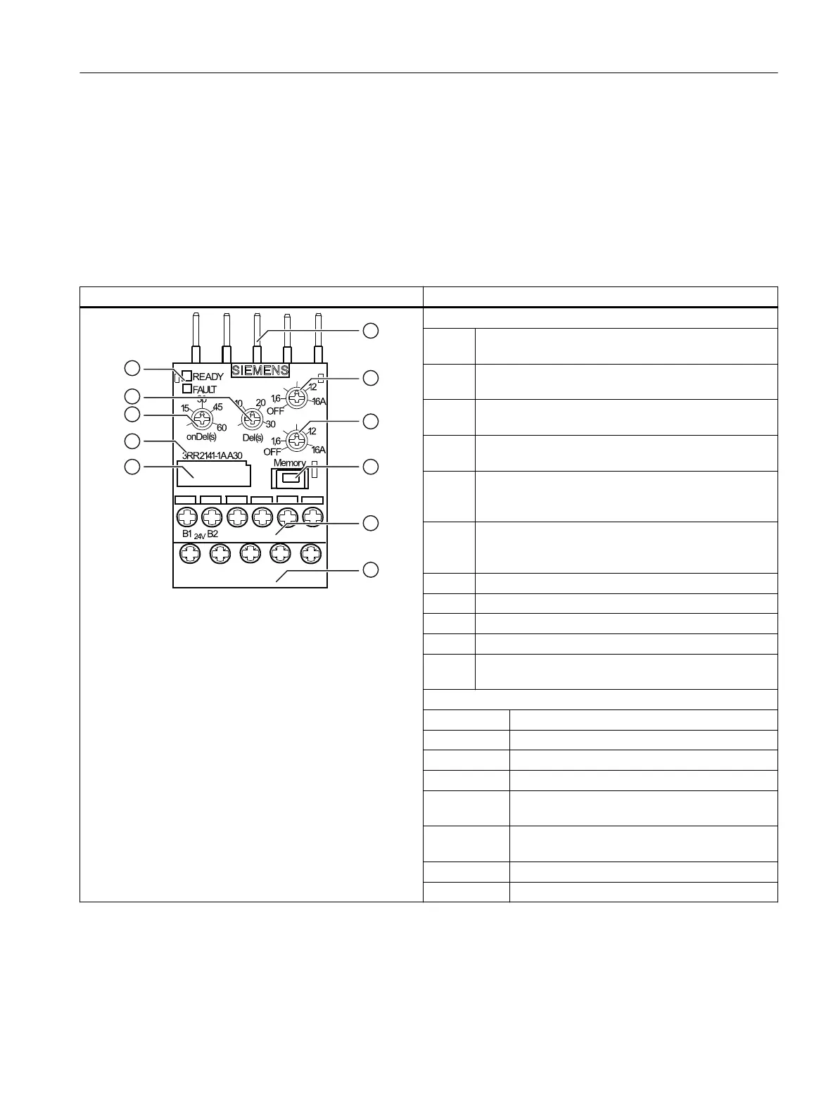
Front view / terminal labeling (basic version)
Front view Description
,Ⴃ
,Ⴍ
a
B
BB
7
7
7
$
2
,
Position digits
① Connection for contactor mounting or for stand-
alone assembly
② Rotary button for setting the threshold for overshoot
"I▲"
③ Rotary button for setting the threshold for under‐
shoot "I▼"
④ Sliding switch "Memory" for selecting the reset re‐
sponse parameter (manual/autoreset):
⑤ Control circuit terminal (removable):
The control circuit can be connected using either the
screw-type or the spring-loaded connection system.
⑥ Main circuit terminal (permanently connected) :
The main circuit can be connected using either the
screw-type or the spring-loaded connection system.
⑦ Label (below which there is a DATAMatrix code)
⑧ Device article number
⑨ Rotary button for startup delay time "onDel (s)"
⑩ Rotary button for tripping delay time "Del (s)"
⑪ Status display via "Ready" LEDs (green) for auxiliary
voltage and "Fault" (red) for switching state
Terminal labels
B1 Supply voltage ∼ / +
B2 Supply voltage ∼ / -
32 Output relay K1 changeover contact NC contact
31 Output relay K1 changeover contact root
34 Output relay K1 changeover contact NO con‐
tact
2/T1, 4/T2,
6/T3
Main circuit terminals
14 / 22 Feed-through contactor auxiliary switch (S00)
A2 Feed-through contactor coil terminal (S00)
You can nd additional information on the connection terminals and the permissible conductor
cross-sections in the Chapter "Connection methods (Page 23)".
You can nd information on connecting in the Chapter "Circuit diagrams (Page 59)".
3RR2 current monitoring relays
4.4 3RR21 current monitoring relays
SIRIUS 3UG4 / 3RR2 monitoring relay
Equipment Manual, 07/2021, NEB927043002000/RS-AD/005 55
 Loading...