6.5 3UG4614 line monitoring relay
6.5.1 Operator controls and connection terminals
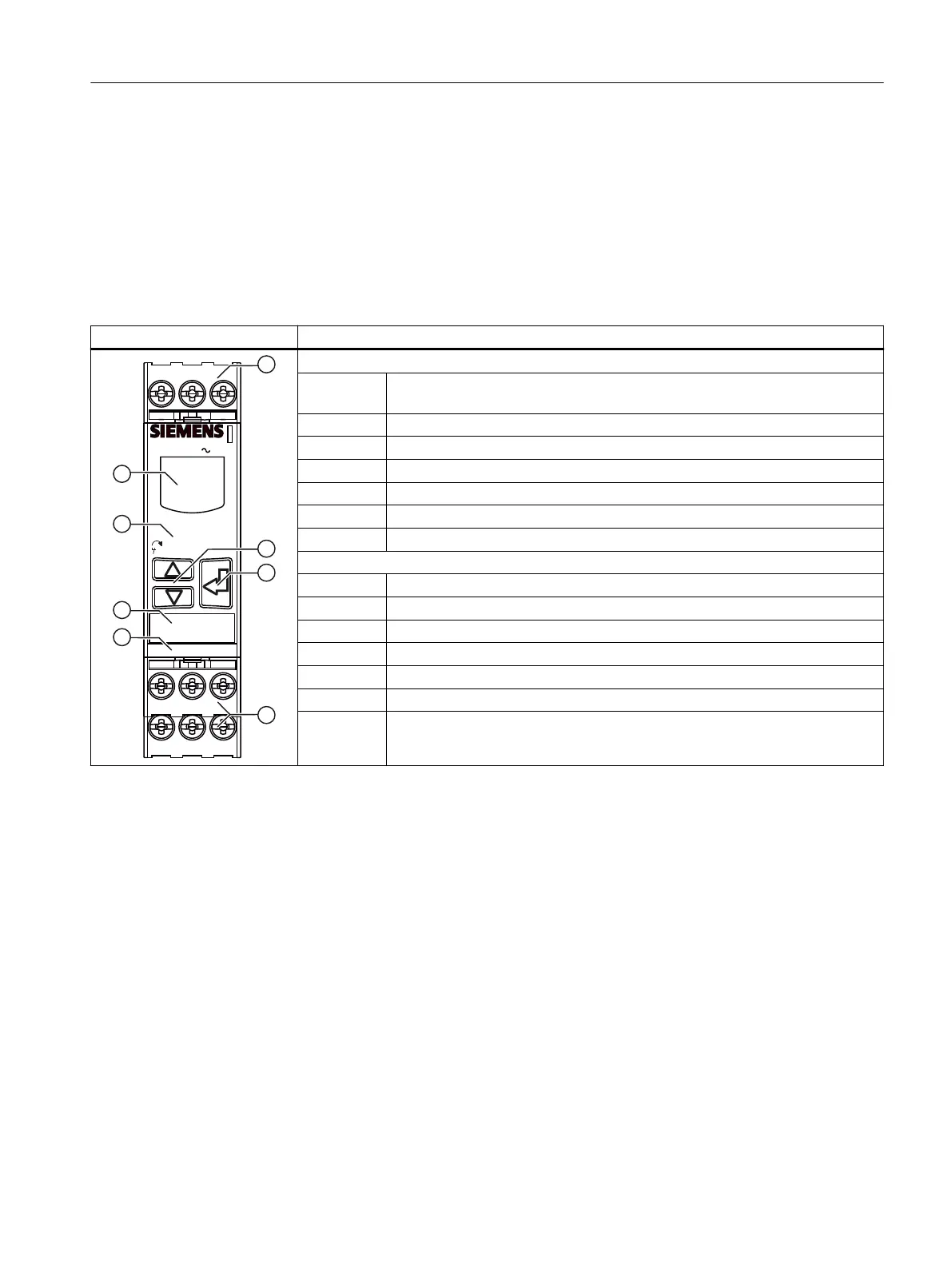
Front view / terminal labeling 3UG4614
Front view Description
24
2122
12
14
11
L3
L2
L1
3UG4614-.....
SIRIUS
3 160-690V
onDel -> Power on delay
Del -> Umin/Asym delay
Mem ? -> Memory?
? -> Phase sequence?
NC -> Circuit principle
Position digits
① Terminal block (removable):
Connection is possible using screw terminals or spring-loaded terminals.
② Arrow keys for menu navigation
③ SET key for menu navigation
④ Device article number
⑤ Label
⑥ Legend for menu
⑦ Display for parameterization, actual-value indication, and diagnostics
Terminal labels
L1, L2, L3 Rated control supply voltage
12 Output relay K1 CO contact NC contact
11 Output relay K1 CO contact root
14 Output relay K1 CO contact NO contact
22 Output relay K2 CO contact NC contact
21 Output relay K2 CO contact root
24 Output relay K2 CO contact NO contact
You can nd additional information on the connection terminals and the permissible conductor
cross-sections in the Chapter "Connection methods (Page 23)".
You can nd information on connecting in the Chapter "Circuit diagrams (Page 102)".
6.5.2 Functions
General functionality
The 3UG4614 line monitoring relays monitor a three-phase system for phase
asymmetry, undervoltage, phase failure, and phase sequence.
The devices feature a wide-range voltage input and are self-powered (measuring voltage
= rated control supply voltage). The 3UG4614 line monitoring relays monitor all phases of three-
phase AC networks from 160 to 690 V through terminals L1 / L2 / L3 and also draw power from
all three phases simultaneously.
3UG4.1 line monitoring relay
6.5 3UG4614 line monitoring relay
SIRIUS 3UG4 / 3RR2 monitoring relay
Equipment Manual, 07/2021, NEB927043002000/RS-AD/005 97
 Loading...